ADJUSTMENT FOR STITCH LENGTH UNIT OPERATED WITH
STEP MOTOR
23
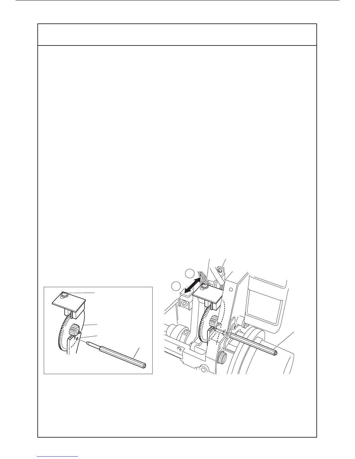
1. Loosen the two set screws "D" (Fig.2). One of the set screw located behind a drawing
(Fig.2)and lower position.
2. Insert guage pin "A" (Fig.1 N0.11684) into the both hole on the gear "B" and "C" (Fig.1)
for the step motor.
3. Tighten the set screws "D" (Fig.2) and pull out the Guage pin "A", after securing proper
instllingof Stitch length unit. At the working test, if st itch length appears as shorter while
LCD display shows stitch length "4" and DF "1", loosen the screw "E" (Fig.2) and adjust
the position of sensor in the "R" direction, so that it may appear larger stitch length.
Tighten the screw "E" after obtaining proper position.
4. On the contrary, if stitch length becomes larger than required length, sensor's position
should be adjusted in the "F" direction (Fig.2) and tighten the screws "D" after securing
right position.
A
C
E
B