ENG
Operating Manual | Attachment and Installation Cooling Units | Multi Controller (MC) – 400 / 460 V, 3~ | 086100124 35/76
4.5.2 DTS cooling unit assembly (side attachment)
4.5.2.1 Making cut-outs for DTS cooling unit
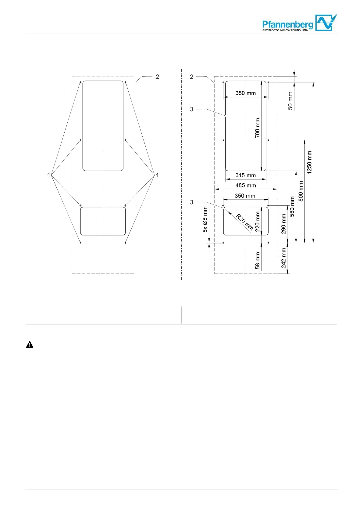
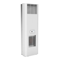
Fig. 11: External view of switch cabinet, assembly bores and cut-outs
1 Holes
2 Device contour
3 Assembly cut-outs
Requirements
DANGER – Danger to life due to electric shock. Make sure that the unit is voltage-free.
• All general requirements are satisfied, see "General", Page 34.
Required tools and materials
• Saw
• Switch cabinet milling machine if necessary
• Protective covers
Procedure
1. Ensure that the switch cabinet has a protective cover to protect against chips.
2. Make cut-outs and assembly holes as shown in Fig. 11.
3. Deburr the cutting edges.
4. Remove chips and assembly waste from the switch cabinet.
The cut-outs and holes are made and the cooling unit can be assembled.