ENG
Operating Manual | Attachment and Installation Cooling Units | Multi Controller (MC) – 400 / 460 V, 3~ | 086100124 45/76
4.6.6 Collective fault signal
The unit is equipped with a potential-free changeover contact for the collective fault signal.
Three connections are provided for connecting the collective fault signal. The terminals are marked with the device tag SK.
4.6.6.1 Connecting the collective fault signal
Prerequisites
DANGER – Danger to life due to electric shock. Make sure that the unit is voltage-free.
Procedure
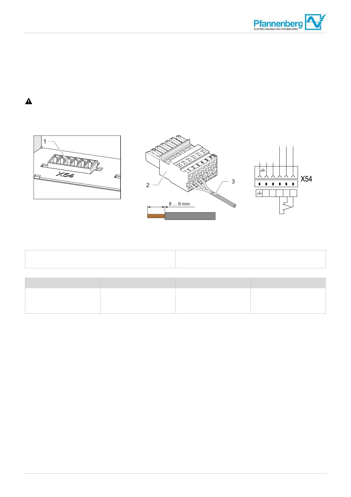
Fig. 19: Connecting the collective fault signal (example)
1 Door contact/fault indication plug X54
2 Mating plug
3 Cable for fault indication, stripping length 8 to 9 mm
Terminals Voltage Current load capacity Version
X54:1 root contact
X54:2 normally closed (NC)
X54:3 normally open (NO)
Maximum 230 V Maximum 1 A Potential-free changeover
contact
Tab. 13: Collective fault signal
1. Connect the collective fault signal (SK) according to the connection plan at the appropriate terminal strip of the controller,
see "Electrical circuit diagram", Page 41.
The collective fault signal is connected.
G00076
Störung/
failure/défaut
2 1
SK
2 1
4 3
5
ok
SKTK TK
6 5 4 3
SK