Mixing pump RITMO L / RITMO M Overview - Operation
Description of assemblies
16
2016-02-17
8 Description of assemblies
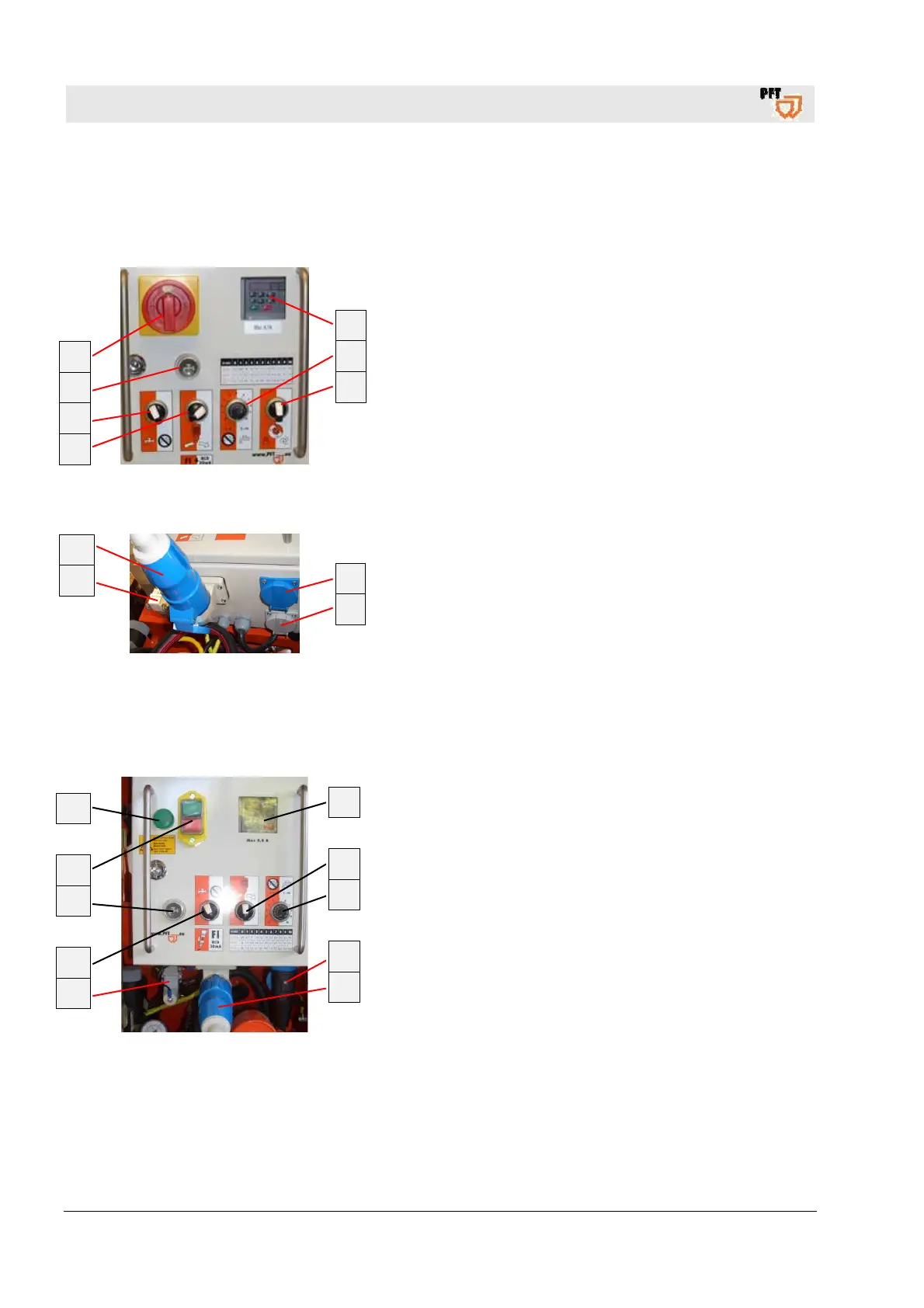
8.1 Overview of the control cabinet RITMO L
Fig. 10: Assembly unit control cabinet
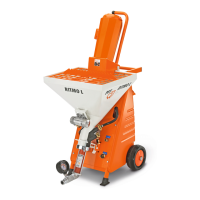
Fig. 11: Connections control cabinet
1. Inspection glass for frequency converter.
2. Poti for motor speed / material quantity.
3. Selector switch vibrating unit “ON / OFF”.
4. Selector switch pump.
5. Selector switch operation with water (as mixing pump),
without water (only as pump).
6. Push button water inlet.
7. Master switch, is also emergency stop switch
.
8. Connection for air compressor 230V (power socket blue
continuous current).
9. Connection for vibrating unit 230V (power socket grey
controlled).
10. Dummy plug / connection remote control.
11. Connection for main current 230V, 1Phase, 16A.
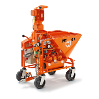
8.2 Overview of the control cabinet RITMO M
Fig. 12: Assembly unit control cabinet
1. Inspection glass for frequency converter.
2. Selector switch pump.
3. Poti for motor speed / material quantity.
4. Connection for air compressor 230V (power socket blue
continuous current).
5. Connection for main current 230V, 1Phase, 16A.
6. Dummy plug / Connection for remote control.
7. Selector switch operation with water (as mixing pump),
without water (only as pump).
8. Push button water inlet.
9. Press button operation “ON / OFF”.
10. Pilot lamp machine ready for operation.
1
2
3
7
6
5
4
8
9
11
10
1
2
3
4
5
10
9
8
7
6