The injection controller is provided with anauto-diagnosis function.
When a failure is detected, the controller:
- turns on the injection indicator (only when itis current).
- enables the engine management check accordingto the data entered in the controller (where possible).
- stores the failure (always).
In the event of intermittent failures, theindicator follows the failure trend and storage remains active. Stored data
areautomatically deleted when the failure does not occur for over 16 usage cyclesof the vehicle (heating -use -
cooling). The battery disconnection does notdelete stored data.
Errors detectable by the auto-diagnosis mayrefer to the following system circuits or sectors of the controller:
- throttle valve position signal
- ambient pressure signal
- cooling fluid temperature signal
- sucked air temperature signal
- wrong battery voltage
- Injector and relevant circuit
- HV coil and relevant circuit
- Stepper and relevant circuit
- Pump relay circuit
- Electric fan relay circuit
- RAM memory
- ROM memory
- EEPROM
- Microprocessor
- Signals panel (stroke -revolution signal
unsteady cycle)
Underlined failures cause the engine to stop.
In the other cases, the engine works managed bythe basic data.
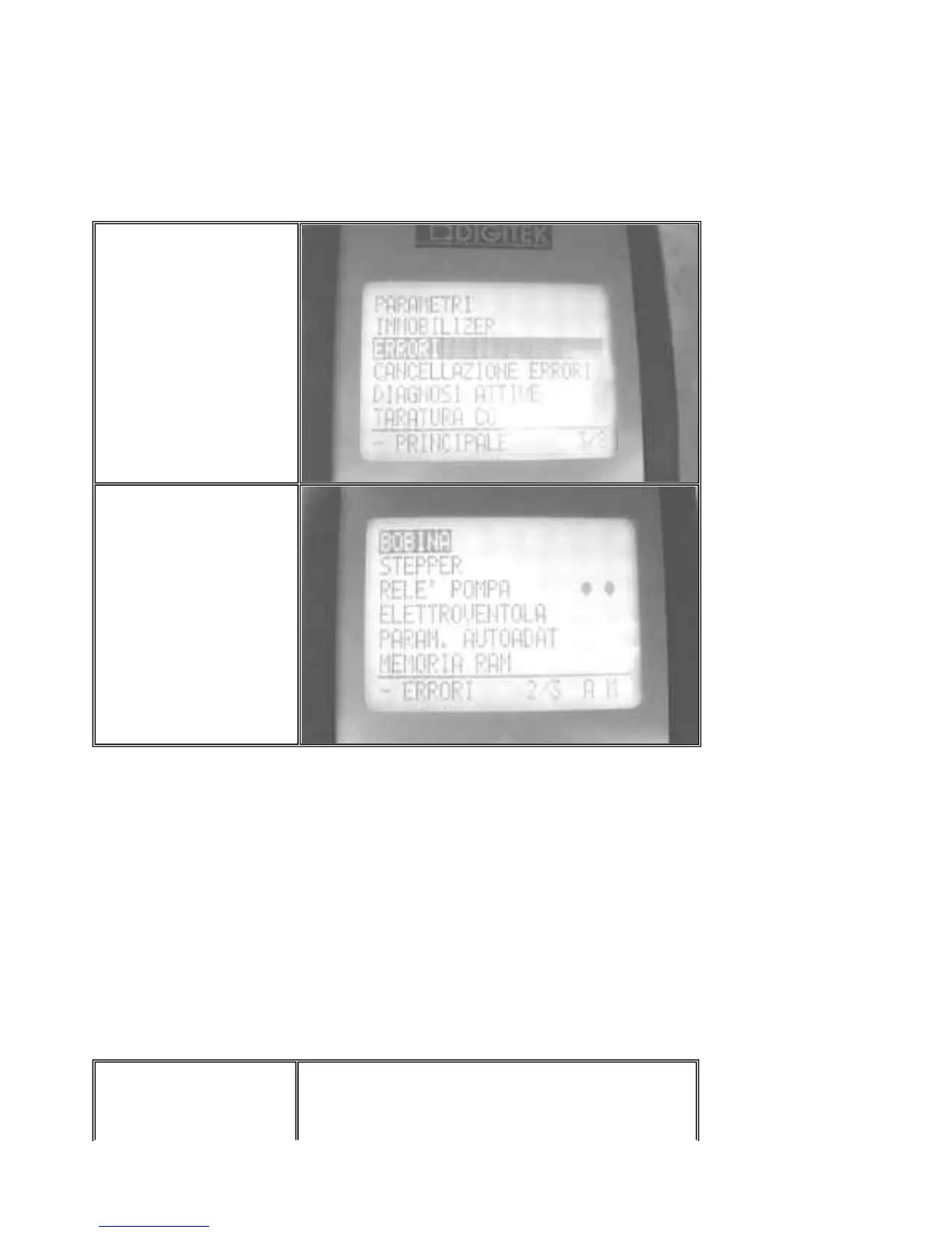
- Checking stored
failures
Connect the diagnostic tester
dwg. 020460Y to the vehicle
system.
Select the menu on the
"ERRORS" function.
The tester pages display the
list of errors detectable by the
auto-diagnosis.
Errors detected by the auto-
diagnosis are marked by one
or two reference dots.
They are arranged on two
lines
Line A = current failures
(present)
Line M = stored failures
- Deleting stored
failures
After fixing any failures,
connect the diagnostic tester
PGO BR-500 ENGINE
P.9-36
Injection indicator circuit



 To Next Page