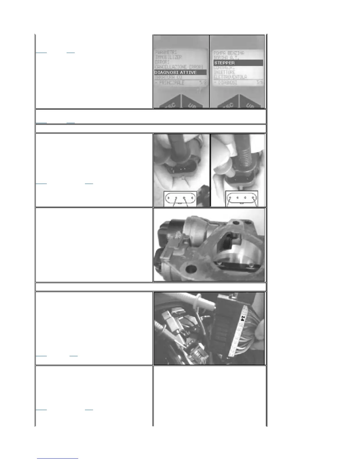
commands some revolution variations and wait
for the diagnostic tester response.
YESgo to 6 NOgo to 8
6
- Test successful. Variations of revolutions perceived.
YESgo to 7?NOgo to 9
7
- Stepper and relevant circuit efficient.
8
- Test failed. No variations of revolutions.
Check the stepper circuit. Disconnect the
stepper connector.
Check the stepper circuit resistance connecting
the tester as shown in the figure. The two
measurements must give the same value.
Resistance = ~ 51 W
YESgo to 11 NOgo to 10
9
- Test successful.
No variations of revolutions.
Remove the throttle body.
Check the auxiliary air circuit cleaning.
Switch from "ON" to "OFF" and again to "ON"
and check whether the piston valve moves. If
the valve does not move, replace the throttle
body.
10
-Replace the throttle body.
11
- Connect the specific tool dwg. 020481Y.
For these checks, do not connect the specific
tool to the controller. Check the continuity of the
4 power supply lines of the stepper.
Light blue-red-14 = 0 Ω (continuity)
B Orange-blue-6 = 0
Ω
(continuity)
C Light blue-yellow-21 = 0
Ω
(continuity)
D Light blue-black-24 = 0
Ω
(continuity)
YESgo to 12 NOgo to 13
12
-Check the earth insulation of the 4
stepper lines
14-23 = >1MW (infinity)
6-23 = >1 MW (infinity)
21-23 = >1 MW (infinity)
24-23 = >1 MW (infinity)
YESgo to 14 NO go to 13
PGO BR-500 ENGINE
P.9-85
Stepper Motor



 To Next Page