13
-Replace or fix the wiring.
YESgo to 11
14
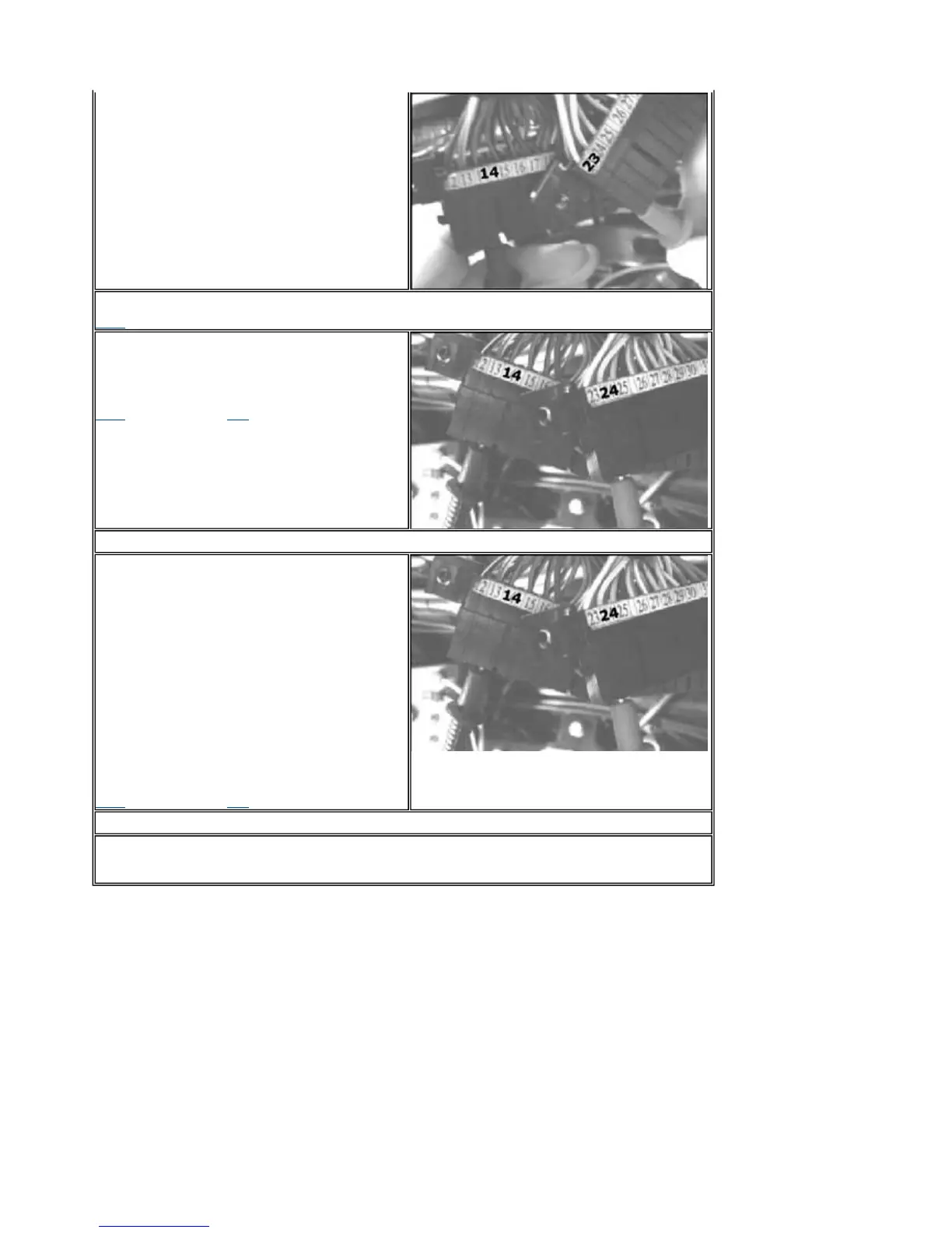
- Connect the stepper connector.
Repeat the continuity check with the tool pins.
14-24 = ~ 51
Ω
6-21 = ~ 51 Ω
YESgo to 16 NO go to 15
15
-Check wiring and connectors more carefully.
16
- Connect the controller connector.
Set the switch to "ON" with switch to "RUN" and
side stand raised. Repeat the "ON" "OFF" "ON"
switching.
Check the presence of voltage pulses on the
stepper command lines.
Setup for direct voltage measurements.
14-24 = V (pulses for a few seconds)
6-21 = V (pulses for a few seconds)
NOTE:
pulses are used to change the stepper
position.
fter reaching the optimum position, the power
supply voltage becomes null.
YESgo to 17 NOgo to 18
17
- The stepper circuit is efficient.
18
-Check the controller connection connector. Replace the controller if needed.
PGO BR-500 ENGINE
P.9-86
Stepper Motor



 To Next Page