Warning:
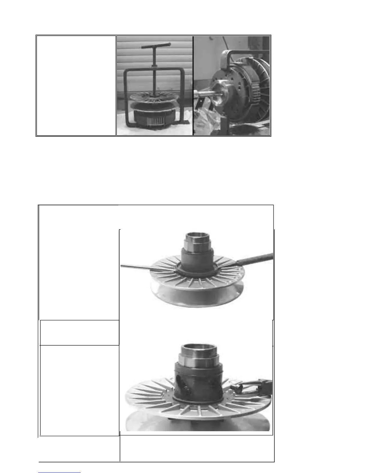
The tool should be strictly secured in a vice usingthe special tail. Do not tighten the rear screw too much as
this could cause anirreversible tool deformation.
- Using the specific 55-mm wrench, remove thefastening ring nut.
- Loosen the tool screw and disassemble thedriven pulley unit, clutch, spring with sheath.
Specificequipment and tools:
Drivenpulley spring compressor: 020444Y
55-mmwrench: 020444Y009
Ring:020444Y010
- To remove the clutch with the
driven pulley it is necessary to
use the specific tool dwg;
- Arrange the tool with the
mean pins screwed in position
"
E
" on the inside;
- Install the driven pulley unit
onto the tool inserting the pins
into the ventilation holes;
- Move the rear stop screw in
abutment against the fixed
driven pulley as shown in the
figure.
PGO BR-500 ENGINE
-Extract the collar using 2
screwdrivers.
-Remove the 4 guide pins.
- Extract the mobile driven half-
pulley.
P.10-7
Automatic Transmission



 To Next Page