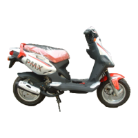
Connection diameterfor lay shaft:
A
= d 20
- 0,01
-0,02
mm
Connection diameterfor wheel axle:
B
= d 30
- 0,010
-0,023
mm
C
= d 15
- 0,01
-0,02
mm
Connection diameterfor shaft
Driven pulley:
D
= d 17
- 0,01
-0,02
mm
E
= d 20
- 0,01
-0,02
mm
F
= d 25
- 0,01
-0,02
mm
- Check that the 3 shafts exhibit no wear or
deformation on the toothed surfaces, at the
bearings and at the oil guards. In case of
faults, replace the damaged parts.
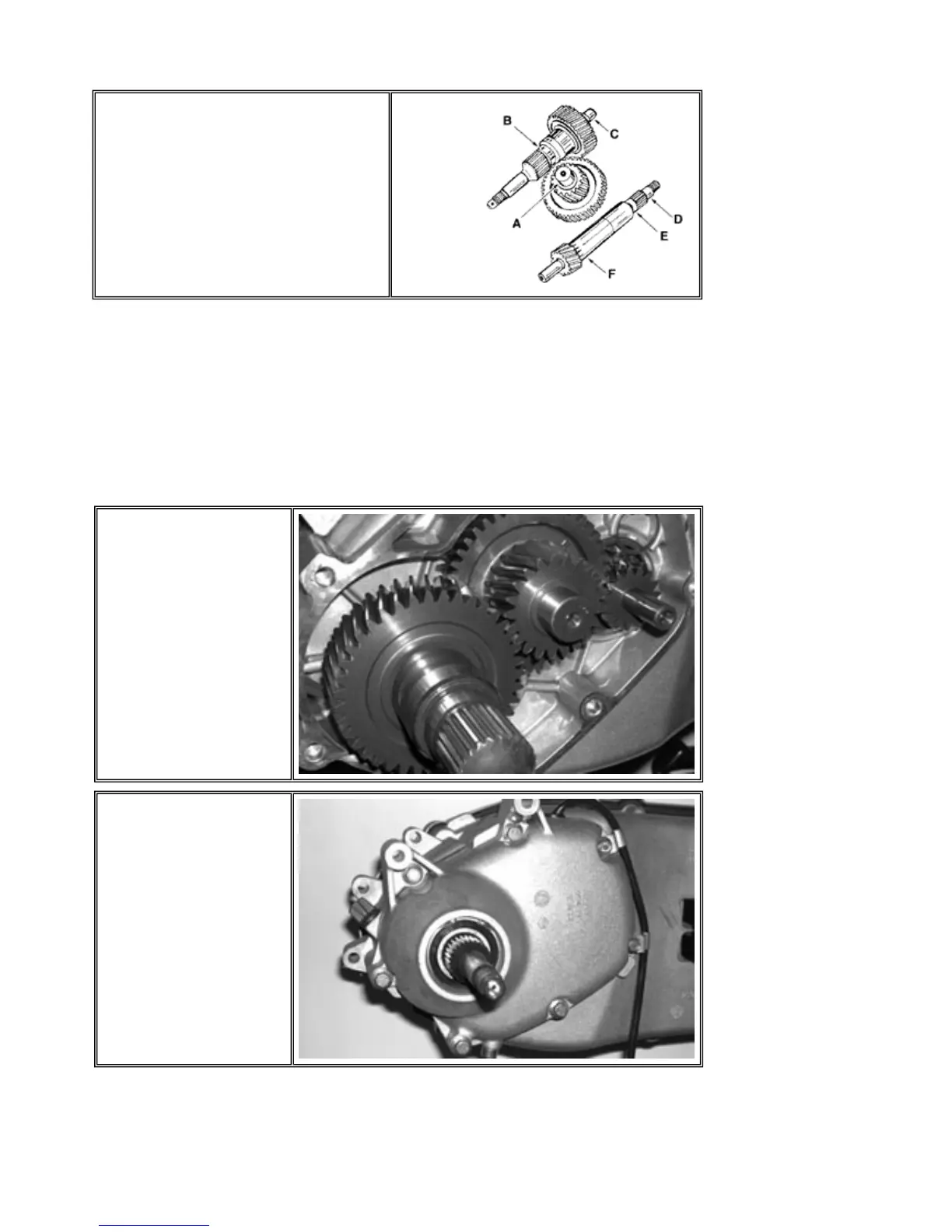
PGO BR-500 ENGINE
- Place the 3 shafts as
shown in the figure.
- Place the 7 fastening screws, tighten them atthe prescribed torque checking the position of the vent pipe sealing
bands andof the 3 shorter screws as shown in the figure
- Refill with the prescribed oil to the maximumlevel.
Tighteningtorque:
Hubcover screws: 24 ~ 27 Nm
Prescribed oil: TUTELA ZC90 Quantity:~ 250 cc
- Check the proper position
of the centering dowels.
- Install a new gasket.
- Install the cover checking
the correct position of the
vent pipe.
P.10-30
Final Reduction
 Loading...