Home
PGO
Scooter
BR-500
Page 86
PGO BR-500 - Page 86
330 pages
Manual
Save Page as PDF
To Next Page
To Next Page
To Previous Page
To Previous Page
Loading...
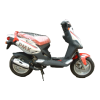
- Loosen the 3 fastening screws.
- Remove the intake manifold unit.
PGO BR-500 ENGINE
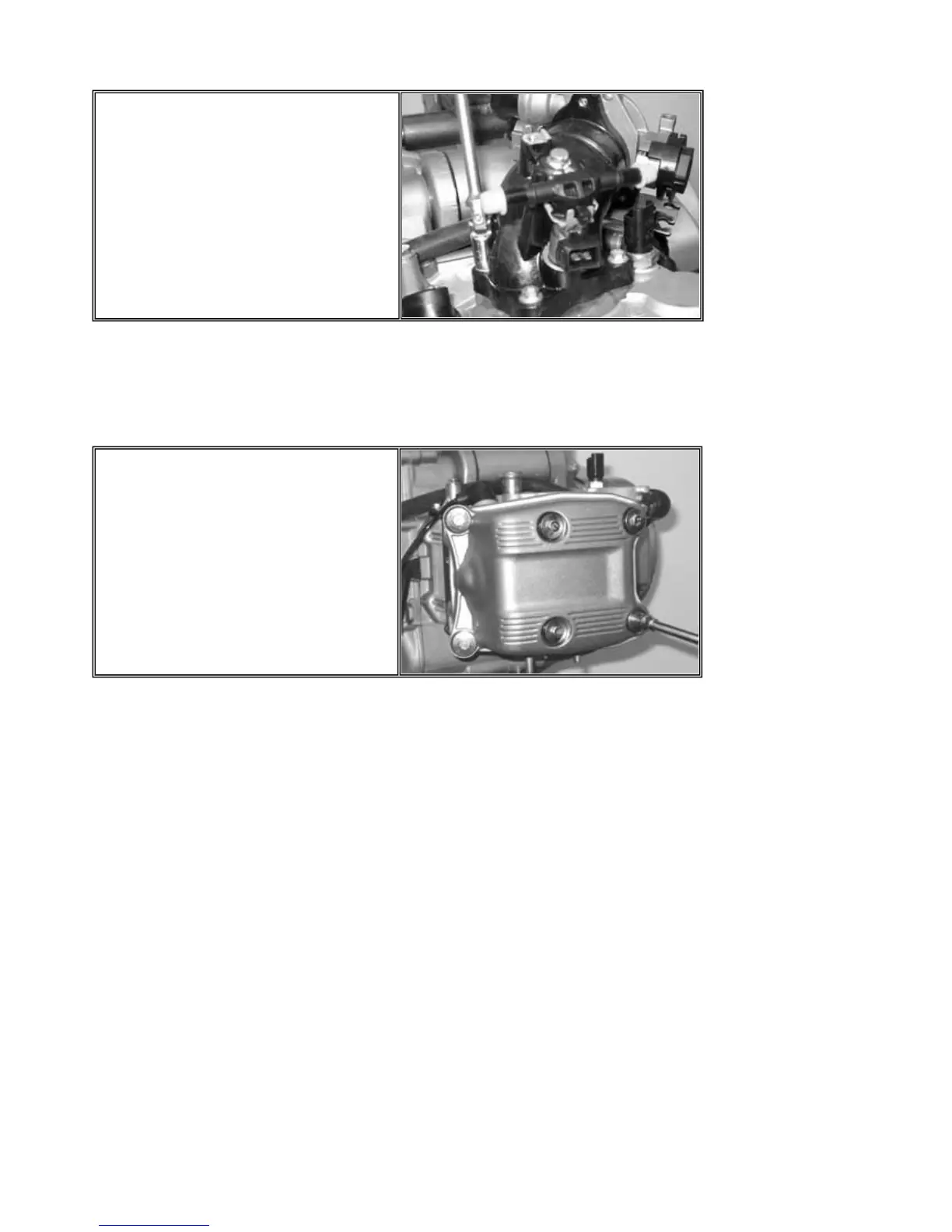
- Loosen the 6 special screws with abutment
and the relevant rubber gaskets.
- Remove the tappet cover w
ith relevant
gasket.
P
.1
0
-
67
Thermal Unit & timing system
85
87
Table of Contents
Main Page
Index of Topics
2
Preface of Standard Operating Time Scale
3
Parts List
4
Assembly Operation Drawing
15
BR-500 Pre-Delivery Inspection
15
Assembly Procedure
16
BR-500 Parts List
17
Locks Inspection
18
Electric System
18
Level Check
19
Table of Contents
20
Automatic Transmission
21
Tightening Torque
35
Final Reduction
41
Flywheel Cover
50
Flywheel Cover
51
Flywheel and Start-Up
71
Thermal Unit and Timing System
83
Crankcase and Driving Shaft
119
Lubrication
141
Introduction
149
EMS Injection System
150
Troubleshooting
152
EMS System Layout
155
Troubleshooting Procedures
156
Immobilizer System
157
Injection Indicator Circuit
181
Fuel Feeding System
185
Revolution Sensor
209
H.V. Coil
213
Ignition Timing
216
Cooling Fluid Temperature Sensor
218
Sucked Air Temperature Sensor
222
Pressure Sensor
226
Stepper Motor
231
Electric Fan Control Circuit
237
Engine Removal
251
Fuel Pump
260
System Description
274
Periodical Maintenance Table
282
Service Information
284
Specifications
284
Cooling System Service
285
Service Gear Oil/Air Cleaner Assembly
289
Service Draining Pcv Tube Oil
290
CLEANING AIR INLET of CVT TRANSMISSION
290
Cleaning Inside/Check Parts
291
SERVICE GASKET of MUFFLER
291
Related product manuals
PGO Big Max 90
45 pages
PGO G-MAX
52 pages
PGO G-MAX 50
275 pages
PGO T-Rex 50
110 pages
PGO PM-NAKED
50 pages
PGO G-MAX200
275 pages
PGO T-REX 125
114 pages
PGO LIGERO-50
97 pages
PGO G-MAX 150
48 pages
PGO G-MAX 125
48 pages
PGO PMX Sport 50
116 pages
PGO Tigra AF-125BAE
95 pages
 Loading...