Meridian 1
10
4. Input/ Output Specification
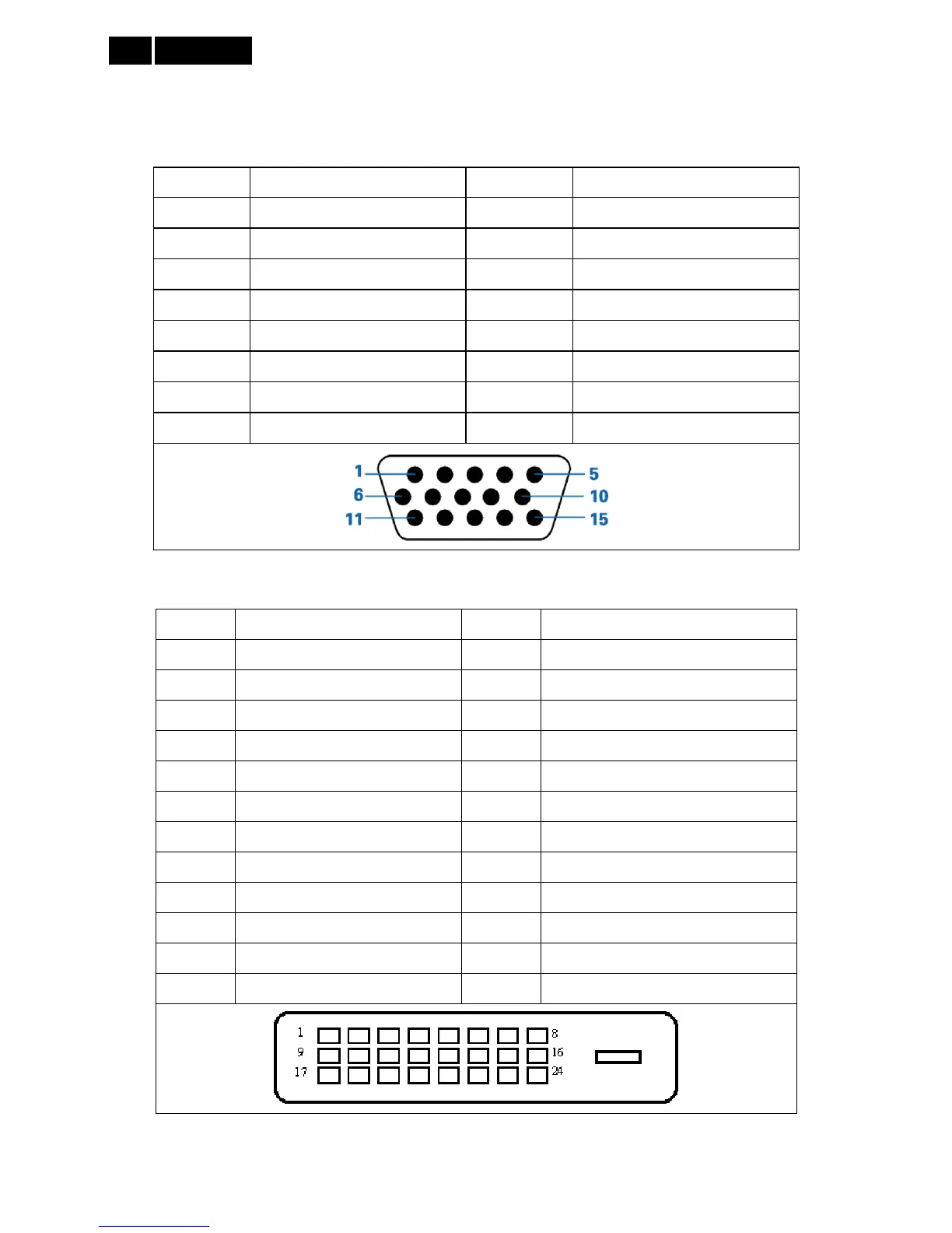
4.1 Input Signal Connector
Analog connectors
Pin No. Description Pin No. Description
1 Red video input 9 DDC +5V
2 Green video input (SOG) 10 Logic ground
3 Blue video input 11 Ground
4 Sense (GND) 12 Serial data line (SDA)
5 Cable detect (GND) 13 H.Sync/ H +V.Sync
6 Red video ground 14 V.Sync
7 Green video ground 15 Data clock line (SCL)
8 Blue video ground
Digital Connectors
Pin No. Signal Name Pin No. Signal Name
1 TMDS Data 2- 13 TMDS Data 3+
2 TMDS Data 2+ 14 +5V Power
3 TMDS Data 2/4 Shield 15 Ground(for+5V)
4 TMDS Data 4- 16 Hot Plug Detect
5 TMDS Data 4+ 17 TMDS Data 0-
6 DDC Clock 18 TMDS Data 0+
7 DDC Data 19 TMDS Data 0/5 Shield
8 N.C. 20 TMDS Data 5-
9 TMDS Data 1- 21 TMDS Data 5+
10 TMDS Data 1+ 22 TMDS Clock Shield
11 TMDS Data 1/3 Shield 23 TMDS Clock +
12 TMDS Data 3- 24 TMDS Clock -