Mechanical Instructions
EN 13Q529.1E LA 4.
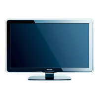
4.3.8 LCD Panel
Refer to next figure for details.
1. Remove the SSB as described earlier.
2. Remove the Bass-midrange speakers as described earlier.
3. Remove the Tweeters as described earlier.
4. Unplug the connectors [1].
5. Remove the fixation screws [2].
6. Remove the fixation screws [3].
7. Lift out the sub frame.
8. The LCD panel can now be lifted from the front cabinet.
When defective, replace the whole unit.
Figure 4-13 LCD Panel
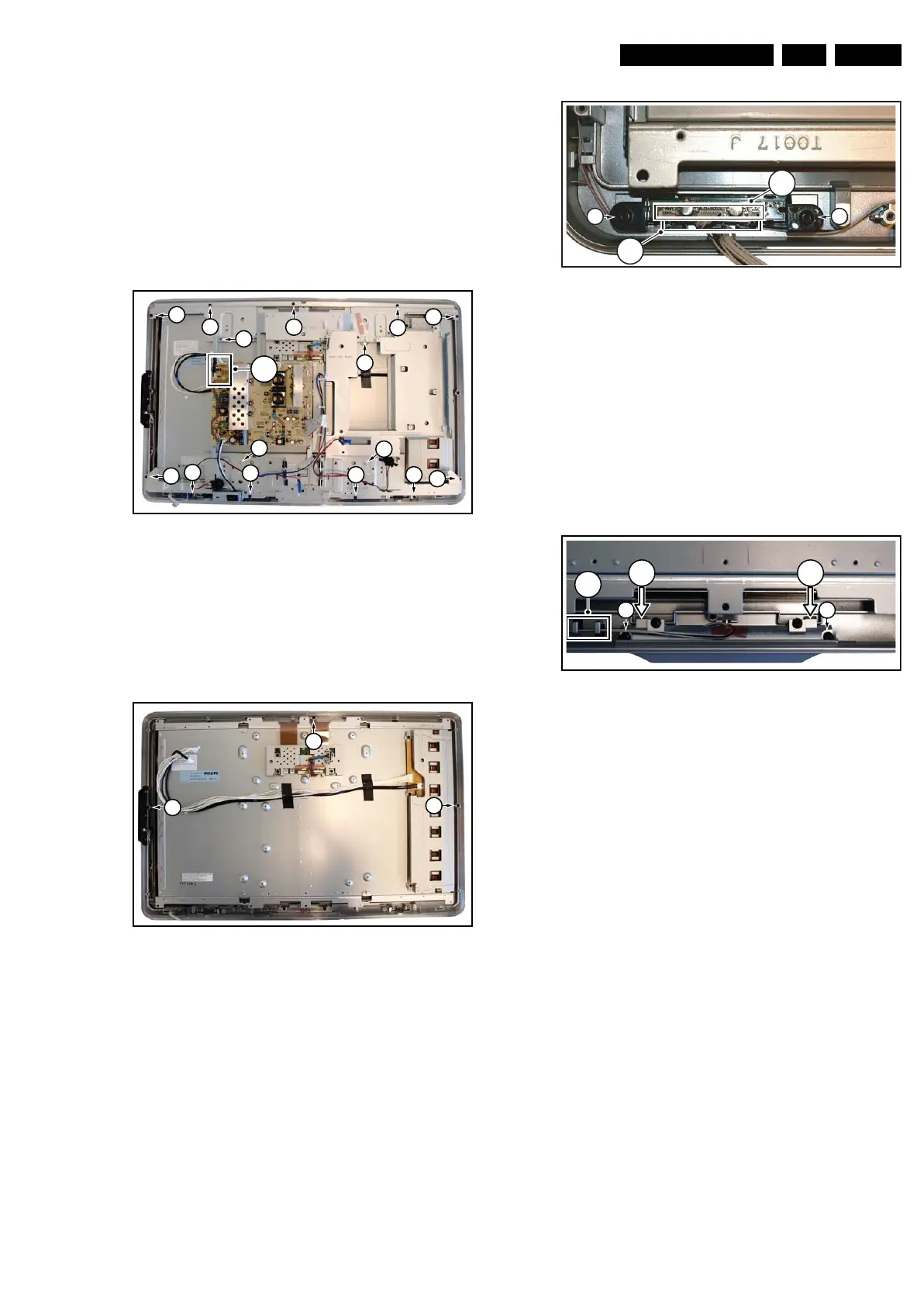
4.3.9 Rim
Refer to next figure for details.
1. Do all steps as described in the removal of the LCD panel
except the last step.
2. Remove the screws [1].
Figure 4-14 Rim
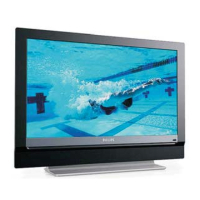
4.3.10 IR & LED Board
Refer to next figure for details.
1. Do all steps as described in the removal of the Rim.
2. Remove screws [1] and lift the IR & LED Board from the
front cover.
3. Lift the board and take it out of the set.
4. Release the cables from the cable clamps.
5. Unplug the connectors [3].
When defective, replace the whole unit.
Figure 4-15 IR & LED Board
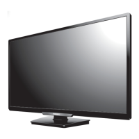
4.3.11 Lightguide
Refer to next figure for details.
1. Do all steps as described in the removal of the Rim.
2. Release the cables from the cable clamps [1].
3. Remove screws [2] and lift the lightguide from the front
cover.
4. Release the board by pushing up the clamps in the
direction of the arrows.
5. Remove the unit from the front cover.
When defective, replace the whole unit.
Figure 4-16 IR & LED Board
4.4 Assy/Panel Removal ME8+ Styling
Refer to the Q528.2E LA Service Manual.
4.5 Set Re-assembly
To re-assemble the whole set, execute all processes in reverse
order.
Notes:
• While re-assembling, make sure that all cables are placed
and connected in their original position. See figure “Cable
dressing”.
• Pay special attention not to damage the EMC foams on the
SSB shields. Ensure that EMC foams are mounted
correctly.
I_17660_115.eps
130308
2
2
3
2
2
2
22
2
2
2
3
3
3
1
(
2x
)
2
I_17660_116.eps
130308
1
1
1
I_17660_117.eps
290408
1
1
2
(
3x
)
2
I_17660_118.eps
140308
2 2
1
3 3