Mechanical Instructions
EN 12 Q529.1E LA4.
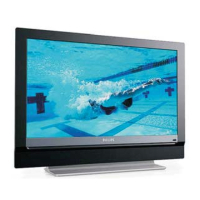
4.3.4 Bass-midrange Speakers
Refer to next figure for details.
1. Release the speaker connectors [1] from unit.
2. Remove the screw [1] and lift the whole unit from the set.
Take the speakers out together with their casing. When
defective, replace the whole unit.
Figure 4-9 Bass-midrange Speaker
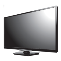
4.3.5 Tweeters
Refer to next figure for details.
1. Remove the bass-midrange speaker as described earlier.
2. Remove the screw [1] and lift the whole unit from the set.
When defective, replace the whole unit.
Figure 4-10 Tweeters
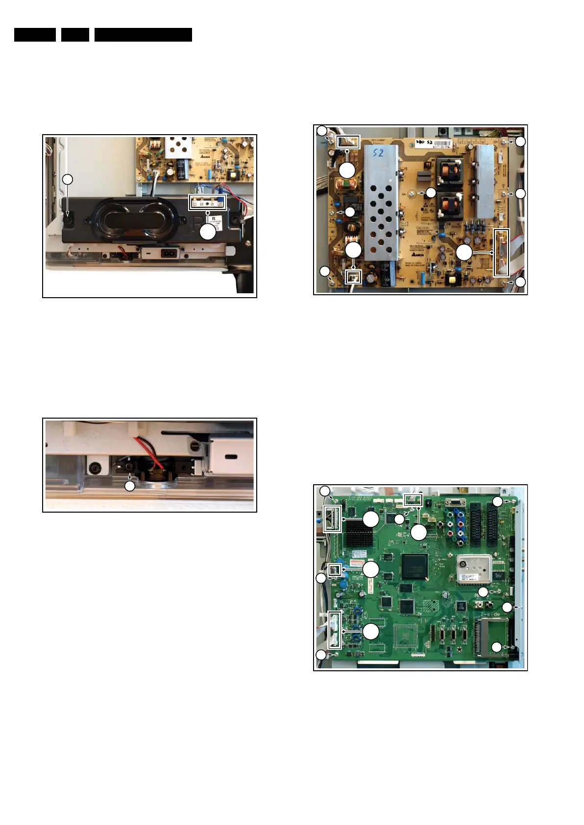
4.3.6 Display Supply Panel
Refer to next figure for details.
1. Unplug the connectors [1].
2. Remove the fixation screws [2].
3. Take the board out.
Figure 4-11 Display Supply Panel
4.3.7 Small Signal Board (SSB)
Refer to next figure for details.
Caution: it is mandatory to remount all different screws at their
original position during re-assembly. Failure to do so may result
in damaging the SSB.
Refer to next figures or details.
1. Unplug the LVDS connector [1].
Caution: be careful, as this is a very fragile connector!
2. Unplug the connectors [2].
3. Remove the screw [3] from the side I/O cover.
4. Remove the fixation screws [4].
5. The SSB can now be taken out of the set.
Figure 4-12 Small Signal Board
I_17660_111.eps
130308
1
2
I_17660_112.eps
130308
1
I_17660_113.eps
130308
1
2
2
2
2
2
2
2
1
2
(
2x)
I_17660_114.eps
130308
4
4
4
4
4
4
3
1
2
2
2
(2x)
4