65BDL3052E/75BDL3052E/86BDL3052E
15
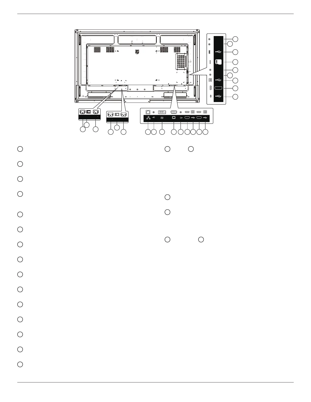
1
AC IN
AC power input from the wall outlet.
2
MAIN POWER SWITCH
Switch the main power between On and O.
3
AC OUT
AC power supply to the AC IN jack of a media player.
4
RJ-45
The LAN control function is used for sending the remote
control signal from the control center.
5
AUDIO IN
Audio input for VGA source (3.5mm stereo phone).
6
DVI-D IN
DVI video input.
7
VGA IN(D-Sub)
VGA video input.
8
AUDIO OUT
Audio output for external AV device.
9
HDMI1 IN
Connect to a source device via an HDMI cable.
10
USB-B-1
Touch connector to HDMI1.
11
HDMI2 IN
Connect to a source device via an HDMI cable.
12
USB-B
Touch connector to HDMI2.
13
USB 3.1 C
Support display and touch function.
14
HDMI3 IN
Connect to a source device via an HDMI cable.
15
USB-B
Touch connector to HDMI3, VGA, DVI-D.
16
IR IN /
17
IR OUT
IR signal input/output for the loop-through function.
NOTES:
• The remote control sensor of this display will stop
working if the jack [IR IN] is connected.
• To remotely control your A/V device via this display,
refer to page 25 for IR Pass Through connection.
18
MICRO SD
Insert a Micro SD card.
19
USB SERVICE PORT
Connect to usb storage device and service port (rmware
update).
Note: It’s for updating rmware only.
20
RS232 IN /
21
RS232 OUT
RS232 network input /output for the loop-through
function.
3.2. Input/Output Terminals
100-240V
50/60Hz 2.5A
1 3
2
65BDL3052E
86BDL3052E
75BDL3052E
100-240V
50/60Hz 2.5A
3 4 5 6 7 8 9 10 11 121
2
AUDIO OUT
AUDIO IN
RJ45
USB-B-1 USB-B-2
HDMI1 IN HDMI2 IN
DVI IN VGA IN
13
14
15
17
18
19
21
16
20
USB 3.1 C
USB-B-3
USB
Service Port
HDMI3 IN
IR-IN
IR-OUT
MICRO SD
RS232
OUT
RS232
IN