Circuit Descriptions, Abbreviation List, and IC Data Sheets
EN 102 A02U AA9.
9.4 HDMI
9.4.1 Introduction
Note: Text below is an summary from the"HDMI Specification"
that is issued by the HDMI founders (see http://www.hdmi.org).
The High-Definition Multimedia Interface is developed for
transmitting digital television audiovisual signals from DVD
players, set-top boxes and other audiovisual sources to
television sets, projectors and other video displays.
HDMI can carry high quality multi-channel audio data and can
carry all standard and high-definition consumer electronics
video formats. Content protection technology is available.
HDMI can also carry control and status information in both
directions.
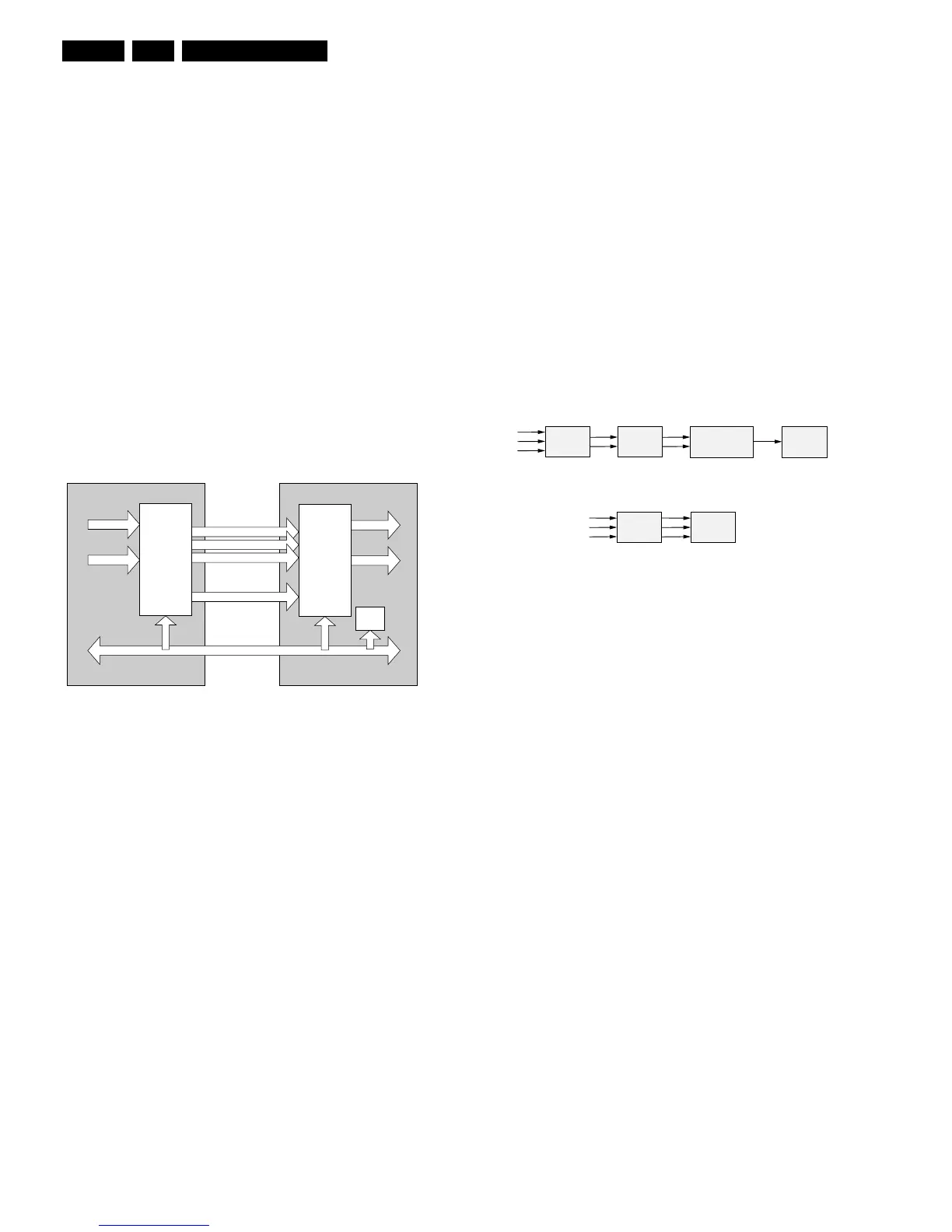
As shown in the HDMI block diagram, the HDMI connector
carries four differential pairs that make up the TMDS
(Transition Minimized Differential Signaling) data and clock
channels. These channels are used to carry video, audio, and
auxiliary data. In addition, HDMI carries a VESA DDC channel.
The DDC is used for configuration and status exchange
between a single Source device and a single Sink device.
Figure 9-5 HDMI block diagram
Audio, video, and auxiliary data is transmitted across the three
TMDS data channels. The video pixel clock is transmitted on
the TMDS clock channel and is used by the receiver as a
frequency reference for data recovery on the three TMDS data
channels.
Video data is carried as a series of 24-bit pixels on the three
TMDS data channels. TMDS encoding, converts the 8 bits per
channel into the 10 bit DC-balanced transition minimized
sequence, which is then transmitted serially across the pair at
a rate of 10 bits per pixel clock period.
Video pixel rates can range from 25 MHz to 165 MHz. Video
formats with rates below 25 MHz (e.g. 13.5 MHz for 480i/
NTSC) can be transmitted using a pixel-repetition scheme. The
video pixels can be encoded in either RGB, YCBCR 4:4:4, or
YCBCR 4:2:2 formats. In all three cases, up to 24 bits per pixel
can be transferred.
In order to transmit audio and auxiliary data across the TMDS
channels, HDMI uses a packet structure. In order to attain the
higher reliability required of audio and control data, this data is
protected with a BCH error correction code and is encoded
using a special error reduction coding to produce the 10-bit
word that is transmitted.
Basic audio functionality consists of a single IEC 60958 audio
stream at sample rates of 32 kHz, 44.1 kHz or 48 kHz. This can
accommodate any normal stereo stream. Optionally, HDMI can
carry a single such stream at sample rates up to 192 kHz or
from two to four such streams (3 to 8 audio channels) at sample
rates up to 96 kHz. HDMI can also carry IEC 61937
compressed (e.g. surround-sound) stream at sample rates up
to 192 kHz.
The DDC is used by the Source to read the Sink’s Enhanced
Extended Display Identification Data (E-EDID) in order to
discover the Sink’s configuration and/or capabilities.
9.4.2 Implementation
HDMI input signals are fed to the HDMI Panellink Receiver
(item 7002 on diagram M1). This IC consists of a flexible audio
and video interface.
The video part delivers RGB/YPbPr output, that directly is fed
to the MPIF source selector on the SSB (The IC is also capable
of RGB input, assuring backwards compatability with DVI).
The audio part delivers a 2-channel I2S digital audio signal that
is fed to the audio DAC (item 7011). After DA conversion the
signals are also fed to the MPIF source selector.
9.5 Video
Figure 9-6 Signal processing A02- versus EMG-chassis.
The SALSA video processing part is a highly integrated
solution. It comprises only two ICs, the ADOC (Analog Digital
One Chip) and the MPIF (Multi Platform InterFace), while in the
R8-chassis, this was handled by four ICs (HIP, PICNIC,
PROZONIC, and HOP).
The MPIF uses a nominal 8 V and 5 V supply, while the ADOC
requires nominal supplies of 1.8 V and 3.3 V.
The video processing of the SALSA system can be spilt into six
parts:
• Initial source selection and analog to digital conversion
performed by MPIF.
• Demodulator (VIDDEC) performed by the ADOC.
• Front End Features (FEF) performed by the ADOC.
• Memory Based Features (MBF) performed by the ADOC.
• Back End Features (BEF) performed by the ADOC.
• Digital Output Processing (DOP) performed by the ADOC.
9.5.1 MPIF Analog Frond End
Introduction
The MPIF (Multi Platform InterFace, type number PNX3000,
item number 7100) is an analog video and audio pre-
processing unit for the ADOC TV processor. It contains the
high frequent IF part and all the analog video and audio source
switching for external in- and outputs. The MPIF can handle
CVBS, Y/C, RGB (1fH/2fH) and YPbPr (1fH/2fH) video signals
as well as stereo, I2S, and second sound IF audio signals. The
MPIF converts the selected video and audio streams from the
analog to the digital domain. Via three high-speed serial data
links (I2D), the digitized audio and video signals are streamed
to the ADOC IC for further processing. Following figure shows
the MPIF block diagram.
HDMI SinkHDMI Source
Video
Audio
Video
Audio
TMDS Channel 0
TMDS Channel 1
TMDS Channel 2
E_13950_062.eps
120304
Transmitter
Receiver
TMDS Clock Channel
Display Data Channel (DDC)
EDID
ROM
HIP PICNIC
MPIF
A02 SALSA
EMG
ADOC
PROZONIC
HOPHOP
CL 36532058_063.eps
271003
Inputs
Inputs