Service Modes, Error Codes, and Fault Finding
EN 16 A02U AA5.
5.6.2 How to Enter
Use one of the following methods:
• Enter the SDM (only via soldering pads marked "FOR
SERVICE" on the SSB). The blinking front LED will show
the entire contents of the error buffer (this works in "normal
operation" mode and in "protection" mode). In order to
avoid confusion with RC5 signal reception blinking, this
LED blinking procedure is terminated when an RC5
command is received.
• Transmit the commands "MUTE", "06250x", and "OK" with
a normal RC (where "x" is the position in the error buffer
that has to be displayed). With x= 1, the last detected error
is shown, x= 2 the second last error, etc.... When x= 0, all
errors are shown.
• "DIAGNOSE X" with the DST (where "x" is the position in
the error buffer that has to be displayed). With x= 1, the last
detected error is shown, x= 2 the second last error, etc....
When x= 0, all errors are shown.
Note: It can take some seconds before the blinking LED starts.
5.7 Protections
5.7.1 Introduction
Fault protections are introduced to avoid unacceptable
temperature rising and burning hazards. If a fault situation is
detected, an error code will be generated and if necessary, the
set is put in protection mode.
The protection mode is indicated by the blinking of the front
LED at a frequency of 3 Hz (or by a coded blinking in special
cases). For the customer, it is made impossible to switch "on"
the set during a protection.
It is possible to determine the type of fault by interpreting the
blinking pattern of the LED indicator. It is also possible to read
out the error codes from the NVM via ComPair. It is possible to
de-activate the protection states in Service Default Mode.
The following protections are implemented:
Table 5-2 Protections overview
The protections are split up in the following order:
• I2C related protections.
• ADOC related protections (via polling on I/O pins or via
algorithms).
• DOP related protections (mainly for deflection items).
• Hardware errors that are not sensed by the OTC (e.g.
vertical flyback protection, bridge coil protection, E/W
protection, arcing protection).
All faults detected are re-checked five times before the
protection mode is triggered. It should be noted that supply
fault detection/protection must be enabled only after the
chassis power supply has been established. Likewise, after the
line drive starts, the deflection detection/protection must be
enabled. To prevent false activation of protection mode during
power mode transitions, interrupts related to supply fault and
deflection fault are disabled.
5.7.2 I2C Related Protections
In normal operation, some registers of the I2C controlled ICs
are refreshed every 200 ms. During this sequence, the I2C
busses and the I2C ICs are checked.
An I2C protection will take place if the SDA and SCL lines are
short-circuited to ground, or to each other. An I2C error will also
occur, if the power supply of the IC is missing.
5.7.3 ADOC Related Protections
If a protection is detected at an ADOC input, the uP will start to
scan all protection inputs every 200 ms for five times. If the
protection on one of the inputs is still active after 1 s, the
microprocessor will put the set in the protection mode. Before
the scanning is started, a so-called "ESD refresh" is carried out.
This is done, because the interrupt on one of the inputs is
possibly caused either by a flash or by ESD. As a flash or ESD
can influence IC settings, the key ICs are initialized again, to
ensure the normal picture and sound conditions of the set.
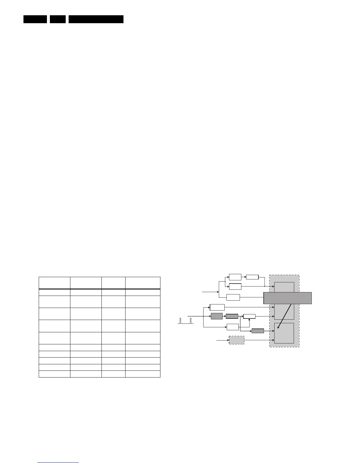
Under Voltage Protection
The under voltage protection is needed due to the non-isolated
chassis architecture used in A02. Whenever there is a short
circuit in the Deflection yoke coil or in the Audio power supply,
the averaged Horizontal Flyback Voltage (HFB_XRAY_PROT)
will fall. After signal conditioning, this voltage is fed to the
"KEYBOARD_ADC" input. When this input of the MIPS
controller is less than a certain level, the under voltage
protection is activated. This is done by the normal keyboard
polling mechanism.
The protection mode is activated after five consecutive
occurrences. Response time required is 2 s. This is to avoid set
going to under voltage protection mode during start up, since
the HFB will only be stable w.r.t. mains on for about 1.6 s.
Figure 5-2 Under Voltage Protection
+8V Protection
Hardware is employed for the detection of +8V supply fault. A
hardware interrupt (MPIF-IRQ) is generated by the MPIF when
the +8V supply falls below the IC specification.
To avoid false detection, the corresponding interrupt sub
routine checks the status of "ASUP" bit in the MPIF status
register for five times consecutively with an interval of 200 ms
before triggering the protection mode. Response time required
is 1.2 s.
Protection Detection
method
Bit name Detection
Under Voltage Via ADC (KB) ADC (KB) ADC input
+8V Supply Via MPIF_IRQ ASUP MPIF internal
register
Horizontal
fly-back
Via interrupts NOHFB ADOC internal
register (DOP)
X-ray Via interrupts XPROT ADOC internal
register (DOP)
Beam Current Via interrupts BCF ADOC internal
register (DOP)
Flash Hardware ctrl - Hardware
Arc Hardware ctrl - Hardware
Vertical Hardware ctrl - Hardware
East/West Hardware ctrl - Hardware
Bridge coil Hardware ctrl - Hardware
-Ve
Threshold
+Ve
Threshold
Signal
conditioning
Switch
MPIF
+8V
Voltage
divider
Signal
conditioning
FLASH
DOP
ADOC
BCL
NOHFB
XPROT
ADC
KEYBOARD
MPIF IRQ
MIPS CORE
EHT-INFO
HFB_X-RAY-
Switch
Inverter
-Ve
Threshold
<16Vp-p
When hor. Defl. coil or sound amp
s/c, HFB will drop at <16Vpp level.
The switch will put ADC keybd to low.
Switch
E_13950_016.eps
040304