Direction for Use
EN 7A02U AA 3.
H
OOKING
UP
THE
T
ELEVISION
4
T
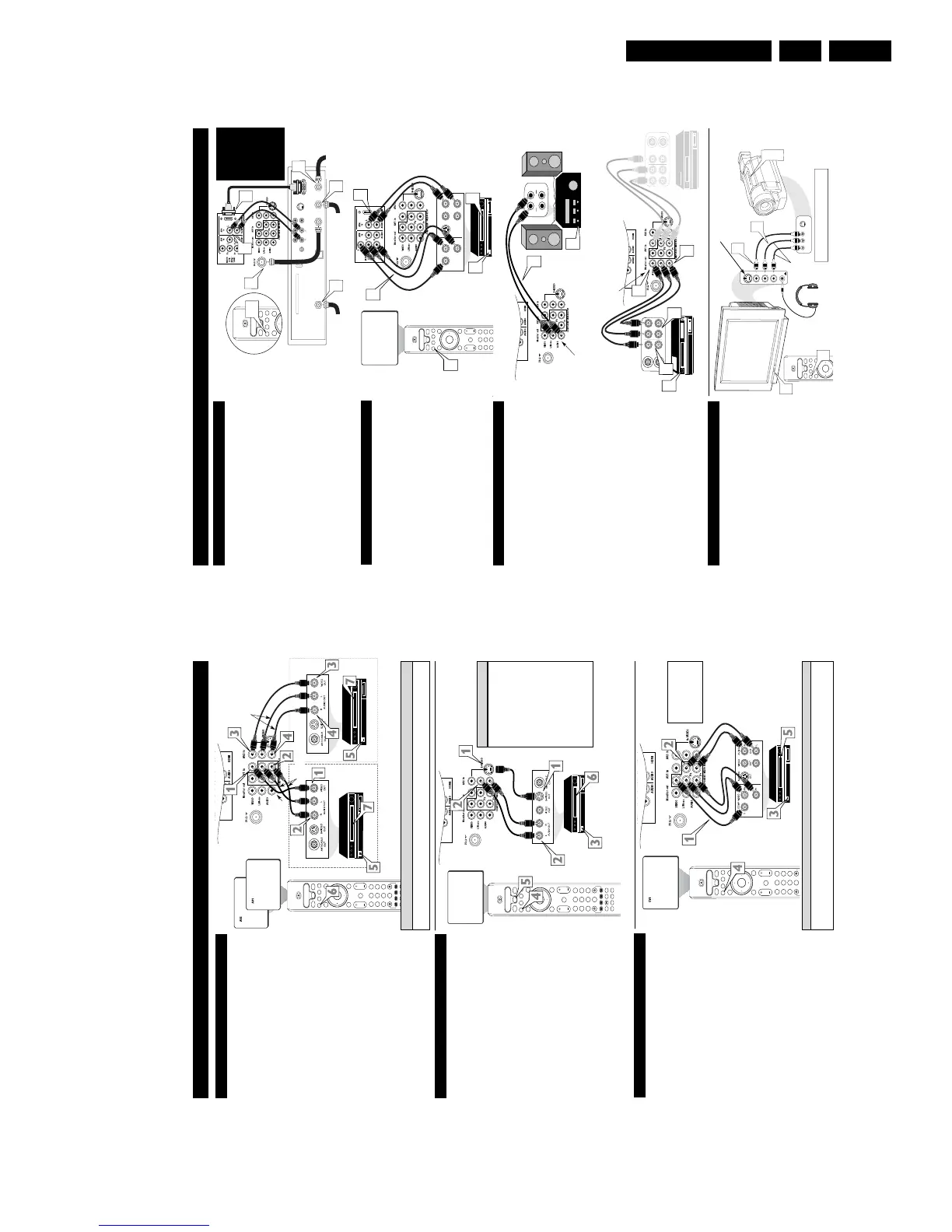
he Monitor (Audio/Video) out jacks are great for recording
with a VCR or used to connect an external audio system for
better sound reproduction.
For Audio System Connection:
1
Connect one end of the R(ight) and L(eft) AUDIO
(Monitor Out) jacks on the TV to the R and L audio input
jacks on your amplifier or sound system. Set the audio sys-
tem’s volume to a normal listening level.
2
Turn the TV and audio system ON. You can now adjust
the sound level coming from the audio system with the
VOLUME (+) or (–) button on the TV or remote control.
For Second VCR Connection/Recorder:
NOTE: Refer to the previous page for the proper hookup of the
first VCR. Follow the instructions on how to tune to the AV 1
channel to view a pre-recorded tape.
The following steps allow you to connect a second VCR to
record the program while your watching it.
3
Connect one end of the yellow Video Cable to the
Monitor out VIDEO plug. Connect the other end to the
VIDEO IN plug on the second VCR.
4
Connect one end of the red and white Audio cable from
the Monitor out AUDIO L and R plugs on the TV to the
AUDIO IN plugs on the VCR.
5
Turn the Second VCR ON, insert a black VHS tape and
it’s ready to record what’s being viewed on the TV screen.
M
ONITOR
O
UTPUTS
AUX/TV INPUT
PHONO INPUT
R
L
1
2
ANTENNA
OUT
ANTENNA
IN
VIDEO
A
UDIO
IN
IN
OUTOUT
LR
ANTENNA
OUT
ANTENNA
IN
VIDEO
AUDIO
IN
IN
OUT OUT
RL
3
4
5
4
3
JACK PANEL
Located on the back of the TV
AUDIO CABLES
(Red & White)
AUDIO SYSTEM
with AUDIO INPUTS
AV OUT
AUDIO L(eft) and R(ight)
JACK PANEL
Located on the back of the TV
AUDIO CABLES
(Red & White)
FIRST VCR
(accessory device)
(Hookup from AV1 on previous page.)
Monitor OUT
VIDEO &AUDIO
L(eft) and R(ight)
SECOND VCR
VIDEO CABLE
(Yellow)
Audio System Connection
Second VCR Connection/Recorder
S
IDE
(AV3) A
UDIO
/V
IDEO
I
NPUTS
A
udio and Video Side Inputs are available for a quick connec-
tion of a VCR, to playback video from an accessory device.
1
Connect the video (yellow) cable from the Video output
on the accessory device to the Video (yellow) Input located
on the SIDE of the TV.
2
Connect the audio cable (red and white) from the Audio
Left and Right Outputs on the accessory device to the
Audio Left and right Inputs on the SIDE of the television.
3
Turn the TV and the accessory device ON.
4
Press the AV button on the remote control to tune the TV
to the side input jacks. “AV3” will appear on the TV
screen.
5
Press the PLAY
䊳
button on the accessory device to
view playback, or to access the accessory device (camera,
gaming unit, etc.).
OK
Select
SLEEP
ACTIVE
CONTROL
CC
AV
CLOCK
PICTURE
SOUND
4
SATVCR AMP ACCDVD
POWER
8
7
3
4
S-VIDEO
VIDEO
AUDIO
In
L
R
AV3
S-VIDEO
VIDEOAUDIO
LEFT RIGHT
1
2
4
3
3
5
Jack Panel located
on the Side of TV
Jack Panel
of Accessory Device
Video Cable
(yellow)
Audio Cables
(red & white)
Optional
Headphones
When headphones re used the sound coming
from the TV speakers will be mute.
T
he AV4 Input Jacks provide HDMI Inputs at 1080i, for accessories
like HD Receivers.
Connect an HD Reviver to the HDMI Input:
Please refer to your Receiver’s Owner’s Manual for more detailed
hookup options.
1
If using a Satellite Dish, Cable signal or Antenna signal, con-
nect the 751 round cable from a Satellite Dish to the SATEL-
LITE IN and/or the Cable and Antenna signals to the ANTEN-
NA “A” or “B” IN on the back of the HD Receiver.
2
Connect another 751 round cable from the OUT TO TV
jack on the HD Receiver to the 751 IN on the back of the TV.
3
Connect a HDMI cable from the HDMI OUT on the HD
Receiver to the AV4 HDMI Input jack on the back of the TV.
4
Connect the Audio L(eft) and R(ight) cables from the
AUDIO Outputs on the HD Receiver to the AV4 AUDIO
Inputs on the back of the TV.
5
With both the HD Receiver and the television ON, Press the
AV button on the remote to tune to the AV 4 Channel and view
the video input from the HDMI supplied signal.
T
he AV5 Input Jacks provide Component Video Inputs for acces-
sories like Digital Video Players.
Connecting a Digital device using the COMPONENT VIDEO
Inputs:
1
Connect the Component (Y, Pb, Pr) Video OUT jacks from
the DVD player (or similar device) to the (Y, Pb, Pr) AV5
in(put) jacks on the TV.
2
Connect the red and white AUDIO CABLES to the Audio
(left and right) output jacks on the rear of the accessory device
to the Audio (L and R) AV5 in(put) jacks on the TV.
3
Turn the TV and the DVD (or digital accessory device) ON.
4
Press the AV button on the remote to tune to the AV5 channel.
5
Press the PLAY button on the DVD (or digital accessory
device) to view the program on the television.
AV 4 I
NPUTS
S-VIDEO
OUT
OUT
OUT
L
R
AUDIO
VIDEO
COMP VIDEO
Y
Pb
Pr
AV5
2
1
3
5
OK
1
2
3
4
5
6
7
8
9
H
Select
SLEEP
ACTIVE
CONTROL
CCAV
CLOCK
MENU
EXIT
PICTURE
SOUND
STATUS
SELECT
4
SATVCR AMP ACCDVD
VOL CH
MUTE
4
OK
1
2
3
4
5
6
7
8
0
9
H
Select
SLEEP
ACTIVE
CONTROL
CCAV
CLOCK
MENU
EXIT
PICTURE
SOUND
STATUS
SELECT
4
TM
SATVCR AMP ACCDVD
VOL CH
MUTE
POWER
8
7
3
4
Coaxial Cable
Lead-in from Cable Outlet,
Converter Box,
or VHF/UHF Antenna
OUT TO TV
SATELLITE
IN
DIGITAL AUDIO
OUTPUT
VCR
CONTROL
S-VIDEO
PHONE JACK
VIDEOAUDIO
L
L
R
R
ACCESS CARD
ANTENNA B
IN
ANTENNA A
IN
Coaxial Cable
Lead-in from
Satellite Dish
Coaxial Cable Lead-in
from Alternate RF
Signal Source
2
1
11
4
5
3
AV5 Component Video Connection
AV4 HDMI Connection
Coaxial Cable
Lead-in from
Satellite Dish
Coaxial Cable Lead-in
from Alternate RF
Signal Source
Coaxial Cable Lead-in
from Cable Outlet,
Converter Box, or
VHF/UHF Antenna
AV 5 I
NPUTS
Model
26PW8402/37 will
not have HDMI
Inputs, it is only
available in the
30PW8402/37,
34PW8402/37,
30PW8502/37, and
the 34PW8502/37.
This TV’s side jack also has an S-Video input. This
can be used instead of the Video cable.
OK
1
2
3
4
5
6
7
8
0
9
H
Select
SLEEP
ACTIVE
CONTROL
CC
AV
CLOCK
MENU
EXIT
PICTURE
SOUND
STATUS
SELECT
4
TM
SATVCR AMP ACCDVD
VOL CH
MUTE
POWER
8
7
3
4
C
omponent Video inputs provide for the highest possible color
and picture resolution in the playback of digital signal source
material, such as with DVD players. The color difference signals
(Pb, Pr) and the luminance (Y) signal are connected and received
separately, which allows for improved color bandwidth informa-
tion (not possible when using composite video or S-Video connec-
tions).
1
Connect the Component (Y, Pb, Pr) Video OUT jacks
from the DVD player (or similar device) to the (Y, Pb, Pr)
in(put) jacks on the TV. When using the Component Video
Inputs, it is best not to connect a signal to the AV1 in Video
Jack.
2
Connect the red and white AUDIO CABLES to the
Audio (left and right) output jacks on the rear of the acces-
sory device to the Audio (L and R) AV1 in Input Jacks on
the TV.
3
Turn the TV and the DVD (or digital accessory device)
ON.
4
Press the AV button to scroll the available channels until
CVI appears in the upper left corner of the TV screen.
5
Insert a DVD disc into the DVD player and press the
PLAY
䊳
button on the DVD Player.
C
OMPONENT
V
IDEO
I
NPUTS
The description for the component video connectors may differ depending on the DVD player or accessory
digital source equipment used (for example, Y, Pb, Pr; Y, B-Y, R-Y; Y, Cr, Cb). Refer to your DVD or dig-
ital accessory owner’s manual for definitions and connection details.
H
ELPFUL
H
INT
T
he TV’s audio/video input jacks are for direct picture and
sound connections between the TV and a VCR (or similar
device) that has audio/video output jacks. Both the AV1 and AV2
Input Jack connections are shown to the right, but either one can be
connected alone. Follow the easy steps below to connect your acces-
sory device to the AV1 and AV2 in Jacks located on the back of the
TV.
1
Connect the VIDEO (yellow) cable to the VIDEO AV1 in
(or AV2 in) jack on the back of the TV.
2
Connect the AUDIO (red and white) cables to the
AUDIO (left and right) AV1 in (or AV2 in) jacks on the
rear of the TV.
3
Connect the VIDEO (yellow) cable to the VIDEO OUT
jack on the back of the VCR (either one or two) or acces-
sory device being used.
4
Connect the AUDIO (red and white) cables to the
AUDIO (left and right) OUT jacks on the rear of the VCR
(either one or two) or accessory device being used.
5
Turn the VCR (either one or two) or accessory device
and the TV ON.
6
Press the AV button on the remote control to select the
AV1 channel for accessory device number one, or the AV2
channel for accessory device number two. AV1 or AV2 will
appear in the upper left corner on the TV screen depending
on the channel chosen.
7
With either of the VCRs (or accessory devices) ON and a
prerecorded tape (CD, DVD, etc.) inserted, press the
PLAY button to view the tape on the television.
AV1 & AV2 I
NPUTS
OK
1
2
3
4
5
6
7
8
0
9
H
Select
SLEEP
ACTIVE
CONTROL
CC
AV
CLOCK
MENU
EXIT
PICTURE
SOUND
STATUS
SELECT
4
PIC SIZE
MAIN
FREEZE
QuadraSurf
TM
PROGRAM
LIST
TV/VCR
REC
SAP
A/CH
SATVCR AMP ACCDVD
VOL CH
MUTE
POWER
8
7
3
4
Note: The Audio/Video cables needed for this connection are not supplied with your TV. Please contact
your dealer or Philips at 800-531-0039 for information about purchasing the needed cables.
c
C
HECK
I
T
O
UT
AUDIO IN
(RED/WHITE)
VCR TWO (or accessory device)
(EQUIPPED WITH VIDEO AND
AUDIO OUTPUT JACKS)
VIDEO IN
(YELLOW)
BACK OF VCR 1
BACK
OF TV
AV 1
Connection
AV 2
Connection
VCR ONE (or accessory device)
(EQUIPPED WITH VIDEO AND
AUDIO OUTPUT JACKS)
AUDIO CABLES
(RED/WHITE)
COMPONENT
VIDEO CABLES
(Green, Blue, Red)
BACK OF TV
ACCESSORY DEVICE
EQUIPPED WITH COMPO-
NENT VIDEO OUTPUTS.
The CVI connection will be dom-
inate over the AV1 in Video
Input. When a Component Video
Device is connected as described,
it is best not to have a video sig-
nal connected to the AV1 in
Video Input jack.
BACK OF VCR 2
AUDIO IN
(RED/WHITE)
VIDEO IN (YELLOW)
T
he S(uper)-Video connection on the rear of the TV can provide
you with better picture detail and clarity for the playback of
accessory sources than the normal antenna picture connections.
NOTE: The accessory device must have an S-VIDEO OUT(put)
jack in order for you to complete the connection on this page.
1
Connect one end of the S-VIDEO CABLE to the S-
VIDEO jack on the back of the TV. Then connect one end
the AUDIO (red and white) CABLES to the AV2 in
AUDIO L and R(left and right) jacks on the rear of the TV.
2
Connect other end of the S-VIDEO CABLE to the S-
VIDEO OUT jack on the back of the VCR. Then connect
the other ends of the AUDIO (red and white) CABLES to
the AUDIO (left and right) OUT jacks on the rear of the
VCR.
3
Turn the VCR and the TV ON.
4
Press the AV button on the remote to scroll the channels
until AV2 appears in the upper left corner of the TV screen.
5
Press the SELECT Button on the remote control to select
the VCR accessory.
6
Now your ready to place a prerecorded video tape in the
VCR and press the PLAY
䊳
button
.
S-V
IDEO
I
NPUTS
OK
1
2
3
4
5
6
7
8
0
9
H
Select
SLEEP
ACTIVE
CONTROL
CCAV
CLOCK
MENU
EXIT
PICTURE
SOUND
STATUS
SELECT
4
ON/OFF
PIC SIZE
MAIN
FREEZE
SOURCE
QuadraSurf
TM
PROGRAM
LIST
TV/VCR
REC
SAP
A/CH
PIP
SATVCR AMP ACCDVD
VOL CH
MUTE
OK
1
2
3
4
5
6
7
8
0
9
H
Select
SLEEP
ACTIVE
CONTROL
CC
AV
CLOCK
MENU
EXIT
PICTURE
SOUND
STATUS
SELECT
4
PIC SIZE
MAIN
FREEZE
QuadraSurf
TM
PROGRAM
LIST
TV/VCR
REC
SAP
A/CH
SATVCR AMP ACCDVD
VOL CH
MUTE
POWER
8
7
3
4
AV2
The S-VIDEO and VIDEO AV2
in(puts) are in parallel. The S-
VIDEO input is dominant when
in use. If separate video signals
are connected to the S-VIDEO
and VIDEO AV2 in(puts), the
signal from the VIDEO AV2
in(put) will not be usable.
Note: The S-Video and Audio
cables needed for this connection
are not supplied with your TV.
Please contact your dealer or
Philips at 800-531-0039 for
information about purchasing the
needed cables.
H
ELPFUL
H
INT
AUDIO CABLE
(RED/WHITE)
VCR
(EQUIPPED WITH
S-VIDEO JACKS)
S-VIDEO
CABLE
BACK OF VCR