Alignments
EN 91A02U AA 8.
Table 8-2 White tone alignment (with color analyzer)
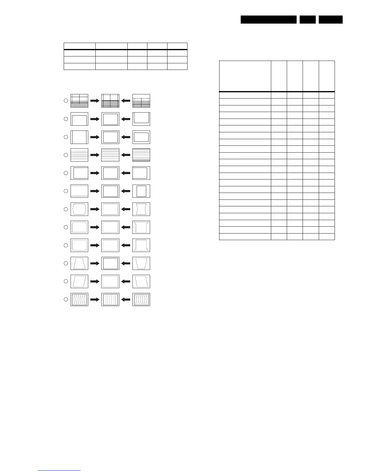
8.3.3 GEOMETRY
Figure 8-3 Geometry Alignments
Notes:
• Set an external pattern generator to a crosshatch video
signal and connect the RF output to the aerial input of the
TV. Set the amplitude at least 1 mV_rms (60 dBuV) and the
frequency to 61.25 MHz. Use system NTSC M if possible,
otherwise match the system of your generator with the
received signal in the set.
Note: Do not use the internal test pattern from the
GEOMETRY menu!
• Use the default alignment settings, but set "Brightness" to
"32".
• For wide screen models, set to "wide screen" mode, for
"classic" models, set to "4:3".
• After alignment, save the value(s) with the STORE
command in the SAM main menu.
Service tip: When the set is equipped with a rotation coil, use
this menu item to check its correct alignment. If alignment is not
correct, go to the user MENU, choose FEAUTURES, and
select ROTATION. With the use of a crosshatch test pattern,
align it to a correct horizontal picture.
Alignment
No adjustments needed. Use the given default values:
Table 8-3 Geometry alignment (default values)
If the mentioned default values do not give the required result,
use the following alignment method:
1. Before starting the vertical alignment, set (in SAM) the
following parameters to "0":
– VER. SHIFT,
– VER. SCOR,
– VER. U_LIN,
– VER. L_LIN.
2. Set SERV. BLK to "on", to blank the lower half of the
screen.
3. Adjust the "VERTICAL SHIFT" potentiometer (R3642 on
the LSP) until the picture is centered (to the mechanical
centre of the picture tube), and switch SERV. BLK to "off".
4. Adjust VER. U_LIN and VER. L_LIN such, that upper and
lower horizontal lines of the crosshatch pattern are just
visible.
Use then the following software regulations to modify the
geometry:
1. VER. AMPL (Vertical Amplitude): Align for the vertical
picture centre, range from -32 to +32.
2. VER. SHIFT (Vertical Shift): Compensating for any gain
error in amplifier, adjust range from -32 to +32 to the proper
amplitude.
3. VER. SCOR (Vertical S-Correction): Align for equal height
of the blocks in the top, the bottom and the middle, range
from -63 to +63.
4. HOR. SHIFT (Horizontal Shift): Adjust for the horizontal
centre of the screen, range from -127 to +128.
Next step is to align the East/West geometry.
1. First, set the parameters EW_5 and EW_6 to "0"
2. EW. WIDTH (East-West Width): This sets the (overall)
horizontal size of the picture on the screen. Range from -
63 to +63 (with the following EW alignments, these lines
can be straightened).
White D mode Temperature DUV x y
Normal 9300 K +-0.003 282 +/- 8 298 +/- 8
Cool 12000 K +-0.003 270 +/- 8 280 +/- 8
Warm 6500 K +-0.003 315 +/- 8 325 +/- 8
E_06532_010.eps
110204
1
2
3
4
5
6
7
8
9
10
11
12
VERT. SLOPE
VERT. SHIFT
VERT. AMPLITUDE
V.S-CORRECTION
HOR. SHIFT
HOR. AMPLITUDE
E/W PARABOLE
UPPER E/W CORNER
LOWER E/W CORNER
E/W TRAPEZIUM
HOR. PARALLELOGRAM
HOR. BOW
Item
27PT8302/37
32PT8302/37
30PW8402/37
34PW8402/37
VERT.SHIFT 0 0 0 0
VER.AMPL -17 8 -15 -8
VER.SCOR 19 12 6 6
VER.U_LIN 0 -3 0 0
VER.L_LIN 0 17 0 0
HOR.SHIFT -54 -69 50 -42
EW.WIDTH -55 -93 45 -40
EW_1 -85 -100 -73 -80
EW_2 -54 -54 -37 -45
EW_3 -31 -10 -19 -25
EW_4 -10 30 -6 -9
EW_5 0 50 0 0
EW_6 0 50 0 0
EW_7 -7 35 -7 -7
EW_8 -27 -1 -22 -24
EW_9 -51 -52 -41 -49
EW_10 -76 -110 -76 -64
HOR.BOW 0 4 2 3
HOR.PARALLEL 0 1 2 1
HOR.LIN 0 -12 0 0
HOR.SCOR 0 0 0 0
HOR.IN_PIN 0 0 0 0