Mechanical Instructions
EN 11BJ3.1E LA 4.
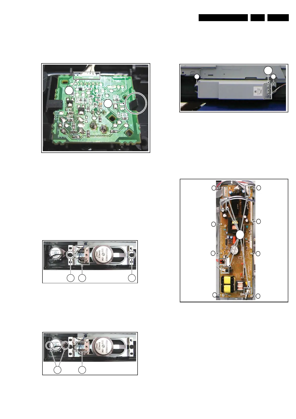
4.3.4 IR & LED Board
1. Refer to next figure.
2. Unplug connector [1].
3. Release clip [2] and remove the board.
When defective, replace the whole unit.
Figure 4-8 IR & LED board
4.3.5 Speakers
This depends on the model/screen size: for the 32” models, the
bare speakers are accessible, while for the larger models they
are encased, and therefore must be replaced as assembly
when defective.
Mid-range Speakers (only for 32” models)
1. Refer to next figure.
2. Unplug connectors [1].
3. Remove screws [2].
Figure 4-9 Mid-range speakers
Tweeters (only for 32” models)
1. Refer to next figure.
2. Unplug connectors [1].
3. Remove screws [2].
Figure 4-10 Tweeters
Speaker box (for 37” and 42” models)
1. Refer to next figure.
2. Unplug connectors [1].
3. Remove screws [2].
When defective, replace the whole unit.
Figure 4-11 Tweeters
4.3.6 Main Supply Panel
1. Refer to next figure (is taken from the 32” model, but the
method is comparable for the other screen sizes).
2. Unplug all connectors [1].
3. Remove the fixation screws [2].
4. Take the board out.
Figure 4-12 Main Supply Panel (32” model)
G_16850_009.eps
110107
1
2
G_16850_010.eps
110107
2 1 2
G_16850_011.eps
110107
2 1
H_16851_011.eps
080307
1
22
G_16850_012.eps
110107
1
2
2
2
2
2
2
2
2



 To Next Page