Mechanical Instructions
EN 13BJ3.1E LA 4.
4.3.10 LCD Panel
This depends on the model/screen size: for the 32” models,
quite some panels must be removed to get access to the LCD
fixation screws, while for the larger models this is hardly
necessary. Therefore, you will find three separate descriptions.
LCD 32” models
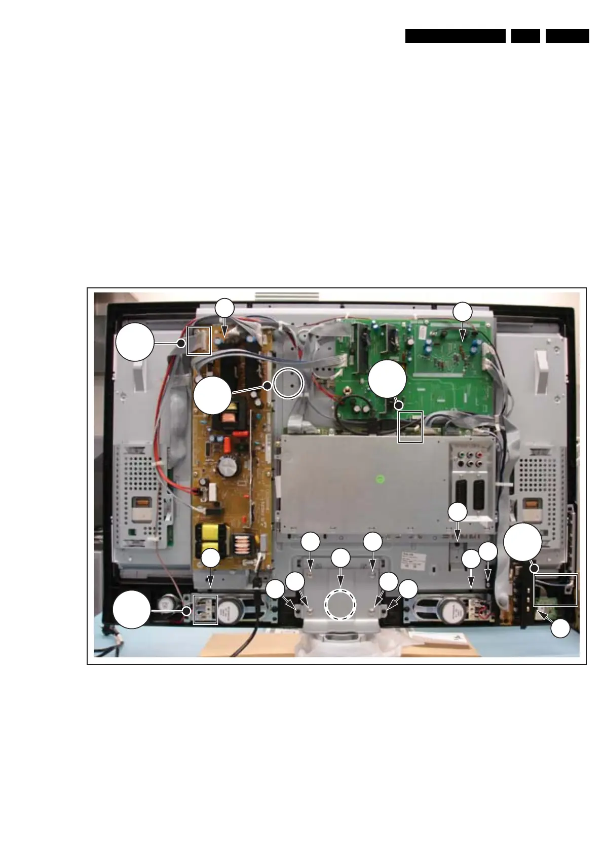
1. Unplug the connectors [1] from the Main Supply Panel, the
LED & IR board, and the Side I/O board.
1. Unplug the outer connectors [2] from the mid-range
loudspeakers.
2. Carefully unplug the LVDS connector [3] on the SSB.
3. Remove the Main Supply Panel, the Standby / Audio Panel
and the SSB as earlier described.
4. Remove fixation screws [4] and put the complete Side I/O
unit on the central sub-frame [6].
5. Remove the stand by removing the fixation screws [8].
6. Remove fixation screws [5] and lift the complete central
sub-frame [6] from the set.
7. Lift the LCD panel [7] from the front cabinet.
Figure 4-16 LCD panel (32” model)
G_16850_014.eps
110107
5
8
8
8
5
5
4
4
5
5
8
5
5
5
2
1
3
6
1



 To Next Page