Mechanical Instructions
EN 15BJ3.1E LA 4.
LCD 42” models
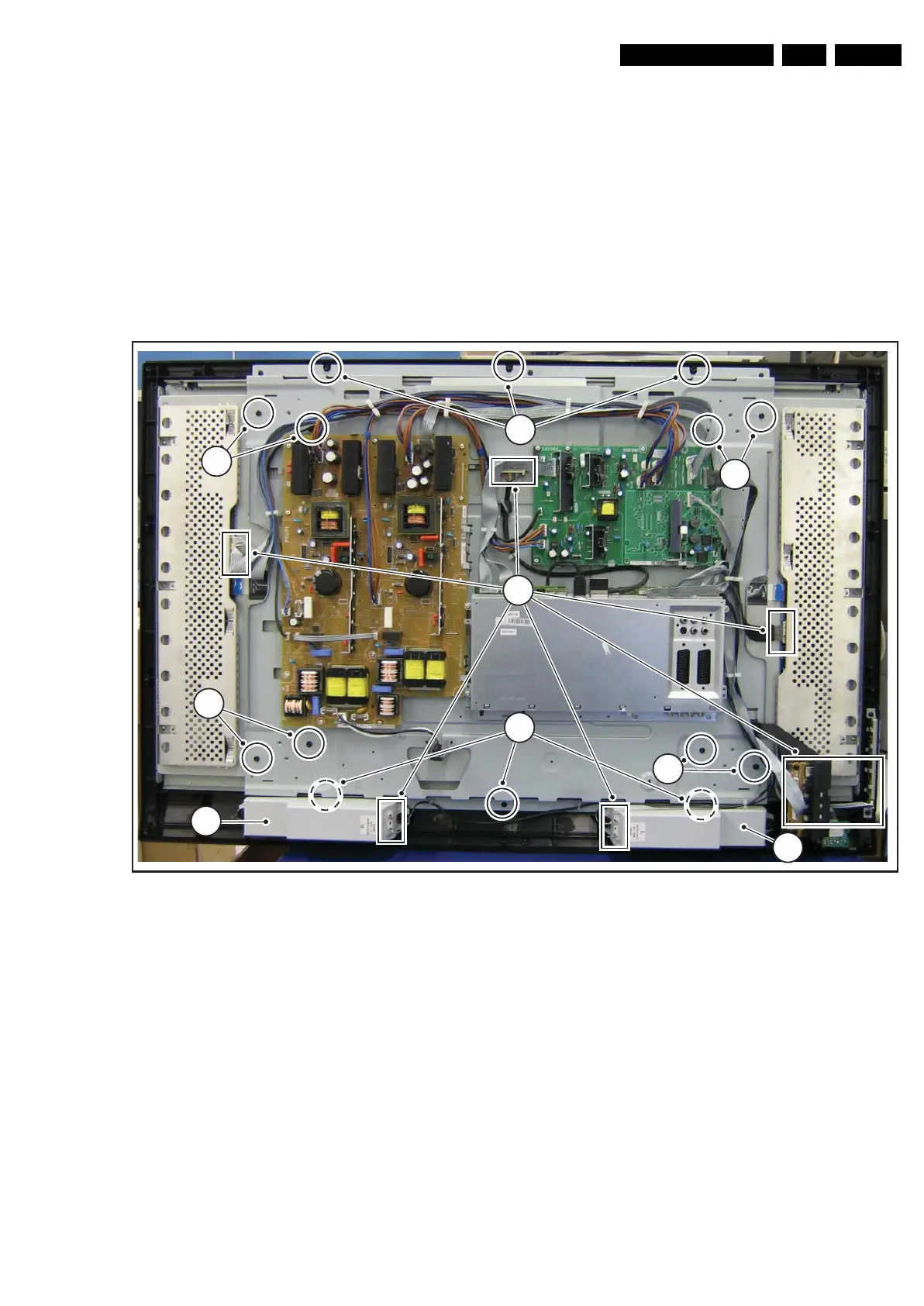
1. Unplug the connectors [1] from the LCD Inverters, the
loudspeakers, the LED/IR board, the Keyboard Control
board, and (carefully) from the LVDS connector on the
display.
2. Remove the speaker boxes [2], to get access to the screws
that hold the lower side of the metal sub-frame.
3. Remove the screws [3] on top and bottom of the metal sub-
frame.
4. Remove and put the complete Side I/O unit on the metal
sub-frame.
5. Remove the T20 fixation screws [4] that hold the LCD
panel and lift the complete metal sub-frame (incl. the
boards and cables) from the set.
6. Lift the LCD panel from the front cabinet.
Figure 4-18 LCD panel (42” model)
4.4 Set Re-assembly
To re-assemble the whole set, execute all processes in reverse
order.
Notes:
• While re-assembling, make sure that all cables are placed
and connected in their original position. See figure “Cable
dressing”.
• Pay special attention not to damage the EMC foams on the
SSB shields. Ensure that EMC foams are mounted
correctly.
G_16851_010.eps
060307
3
3
4
4
4
2
2
1
4



 To Next Page