Service Modes, Error Codes, and Fault Finding
EN 40 BJ3.1E LA5.
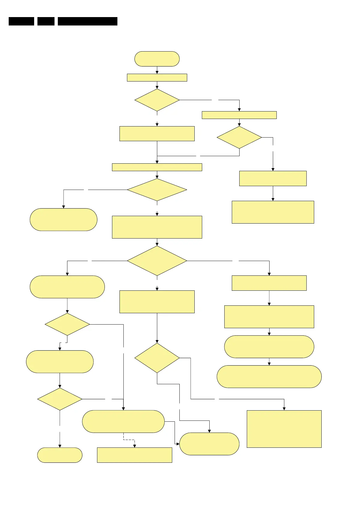
Figure 5-20 Power supply start-up behaviour (for 37” models)
Power Supply Check
37" LCD
Power Supply Start-up Behaviour
Mains cord is connected
+5V2 is OK?
Pin 7 1M46
Check Standby supply
Check Fuse 1400, on Diplay supply
400VF = 295V on fuse 1P03
Drive circuit, T 7S02
and components in standby supply
LED is on?
Check if vacation switch is closed
Red LED is on and +5V2 is ok.
Standby supply is working
Y
No
No
Switch set on via Local keyboard or RC
+5V-SW, +12V, & +8V6 becomes available
from platform supply
Check on connector 1M46
Y
Y
Display supply starts-up
Relay on Display supply is closed
LLC supply starts
Power OK platform
pin 2 1M03 is OK?
LLC supply
is working?
Check OVP Latch
+25V Hot and 400V Hot
LLC supply components, control
circuit....
Check PS in stand-alone mode
(disconnect display supply
connectors)
Check platform supply
Drive 7P27, Vcc = 15V
Switch on control part 7P12 & 7P26
Y
Check output voltage.
LCD Inverter start up process
from SSB.........
N
No
Y
SSB Start-up process
DC/DC converters start up via
Standby processor
Standby line goes
low pin 7 1M03
SSB Board defective
Standby command linefrom PNX
BLR Procedure
N
Y
No start-up of platform sypply check
+Vaux from standby supply
If protection blinking LED
Check protection error code = xx xx xx
is related to platform supply
Check if error code is related to
DC/DC converter on SSB
Error code is
from DC/DC ?
Protection?
Blinking LED?
Y
Change SSB
BLR procedure
Y
SSB Start-up process Continue
Viper & I2C commands
switching VDisplay voltage to LVDS
connector
No
No
Disconnect PS connector To Audio if error code is
Audio protection.
Disonnect PS to Ambilight 1M10 & 1M18.
Try again
In case of short circuit on VDisplay
PS, disconnect LVDS cable
H_16851_005.eps
080307
 Loading...