Service Modes, Error Codes, and Fault Finding
EN 39BJ3.1E LA 5.
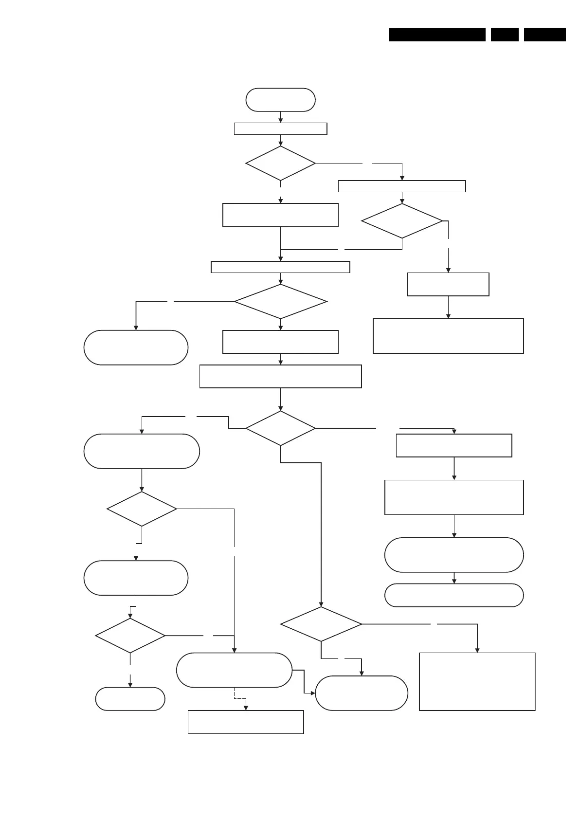
Figure 5-19 Power supply start-up behaviour (for 32” models)
Power Supply Check
32" LCD
Power supply start-up behaviour
Mains cord is connected
+5V2 is OK?
Pin 7 1M46
Check Standby supply
Check Fuse 1400 & 1401 , on Mains filter supply
Drive circuit 7100 & T 7102
and components in standby supply
LED is on?
Check if vacation switch is closed
Red LED is on +5V2 is ok.
Standby supply is working
Y
No
No
Switch set on via Local keyboard or RC
+12V, & +8V6 becomes available connector 1M46
+24V (or 295V) for Backlights connector 1319
Y
Relay on Display supply is closed
LLC supply starts
LLC supply
is working?
Check OVP Latch
LLC supply components, control
circuit....
Check PS in standalone mode
(disconnect display supply
connectors)
Check LLC Display supply
Drive 7001, Mosfet 7005, 7006
OVP Latch
Check output voltage.
LCD Inverter start up process
from SSB.........
N
Y
SSB Start-up process
12V and 5V switched to DC/DC
converters on SSB start up via
Standby processor (PNX)
Standby line goes
low pin 7 1M03
SSB Board defective
Standby command linefrom PNX
BLR Procedure
N
OK
No start-up of Display supply check
Check 25V Hot, 400V Hot
If protection blinking LED
Check protection error code = xx xx xx
is 12V or DC protection(Audio)?
If protection blinking LED.
Check if error code is related to
DC/DC converter on SSB
Error code is
from DC/DC ?
Protection?
Blinking LED?
Y
Change SSB
BLR procedure
Y
SSB Start-up process Continue
Viper & I2C commands
switching VDisplay voltage to LVDS
connector
No
No
Disconnect PS connector to Audio part &
backlight inverters. Try again
In case of short circuit on VDisplay
PS, disconnect LVDS cable
Voltages on
1M46?
Not OK
G_15970_032.eps
120506
 Loading...