Service Modes, Error Codes, and Fault Finding
EN 38 BJ3.1E LA5.
Foot notes for figure “General fault find tree [1/2]”:
1. Observe set behaviour when connecting to mains, and
start-up. First observe front LED during start-up.
2. If LED is red, the Stand-by Supply is operating. TV is in
Stand-by, and this part of Stand-by Processor is running.
3. If LED is green or blue, the Stand-by Supply and Platform
Supply seem to be operating. SSB is started up, DC/DC
converters are working. No protection.
4. When LED is blinking, means set is in protection.
Protection from Power Supply, DC/DC converter, Audio
DC protection, or Display Supply. Read error code via
blinking LED fur further diagnose.
5. Two LED’s on, probably Stand-by Processor has no
software, or wrong software was installed (16-bit / 8-bit).
Reflash correct Stand-by Software via Hyper Terminal.
6. Even if there is “no picture”, but CSM log file is written on a
USB memory stick, we can conclude that the control part is
working; Viper (=main processor) is working. In the CSM
log file we can find the display code (= Option Byte 5) and
other data for diagnosis (as option codes, error codes, etc).
7. Initialise complete set. If red or green LED is switched “on”
(and “off”) by reconnecting mains, it means that the Power
Supply is still alive. Possible cause is a protection on the
PSU (OVP). What about the relay on the PSU? If no
reaction from PSU, check fuses, Standby Supply …….
defective Power Supply, try to disconnect Audio and/or
AmbiLight.
8. The UART log file will give some indications about the start-
up process and failures. In SAM, the “Software and
Hardware Event” log, will give an indication when
intermittent faults occur. Execute the Elpida Memory test,
in case of an intermittent fault or temperature dependent
fault, to check the Viper Dram memories.
9. In particular w.r.t. the “Display code”, a wrong Display code
will result in an incorrect picture format, pixel shift, etc. In
case of “no display”, observe the AmbiLights; if they are
working, we can conclude that the backend of SSB is okay,
except the LVDS part and/or the Display Power Supply.
10. If the +5V Stand-by supply voltage is present, and the set
is not operating, it is possible that the wrong Stand-by
software was installed (16-bit / 8-bit) or Stand-by Processor
is not okay (check 16 MHz CLK). Stand-by line must be
“low” to start-up the set.
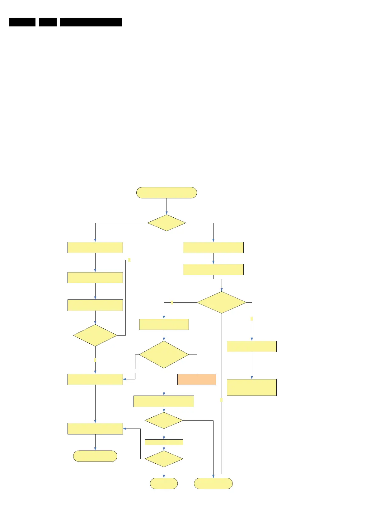
Figure 5-18 General fault find tree [2/2]
Audio is OK
Display remains dark or no picture
Ambilights?
Ambilights are workingAmbilights are not working
Monitor UART, check if Power
state 4 is reached
Check PS
Check Backlight control and
Display Power Supply
Display LVDS Power Supply
Connect USB Memory and go to CSM
Read CSM Log file on a PC
Colour bar test
pattern displayed?
Update software and program correct
Display option code If needed
Display and Back-end is
OK
N
N
Y
Change SSB
SSB Back end defective
Install Jett Software
Use ComPair Quick tests
Display is working?
Y
N
Check LVDS Cable and PS on LVDS
Check Display option
and Software version
Not
OK
Is OK
Display is
Working?
Check LVDS wave form
Wave form?
Display defective
Error codes related to
Display or Display Supply
H_16851_007.eps
080307
 Loading...