76
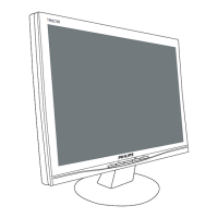
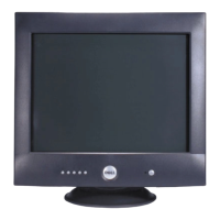
Dell P1230 M25P
Circuit Description
Go to cover page
1. GENERAL DESCRIPTION
The P1230 using 22 flat AGCRT is real Digital ControlledAuto-
scan Color DisplayMonitor withhigh resolution which can operate
horizontal scan frequencyfrom 30KHz up to 130KHz, and vertical
scan frequencyfrom50to 160 Hz.
P1230 is equippedwith an embeddedmicro-controller to provide
required preset modes andwell adj
ustedbyfactory then stored the
data into EEPROM, it also provides manyfunctions, such as digitally
adjustablepicture, power management, sRGB, low emission,high
immunity, DDC2B ---- etc.
This monitor complies with TCO99/TCO03 low emission
standard, E2000 automatic power saving requirements, to
reduce power consumption less than 2 watts i n power saving
mode, also fulfill VESA standard and energy star computer
program of the EPA.
2. DESCRIPTION OF CIRCUIT DIAGRAM
This description briefly introduces the functions including power
supply, power saving management,horizontal/verticaldeflection,
video amplifier,micro-controller and purity and convergence control,
etc.
A. POWER SUPPLY / POWER SAVING MANAGEMENT
The monitor is designed to adopt switching modepower supply
which can operate mains input from 90VACto264VA
C, this
switching power supply applies an IC (STR-F6656 or STR-F6456)
for QUASI-RESONANT MODE controller, that power MOSFET is
packed insideaswell. The control scheme transformsaswitching
converter from avoltage source into a multi-output voltage, the
control concept is exhibitedmanydesirable properties such as
inherent over-loa
d protection, stableandfast system response, the
maximum power delivery is up to 180 watts, then to be limitedby
limiting circuit for safety reason, secondaryfeedback via a photo-
coupler is used to obtain a stable output voltage, the multi-outputs
supply all necessary voltages to defl
ection, video and rest except
micro-controller.
Inorder to meet new requirement of E2000 - power consumption
less 2watts @ off mode, an extra second power supply is adopted,
this 2
nd
power applies SOPS technology, not only supply the +5V to
micro-controller, it is also used to start up the main power supply
mentioned above, suchdesign concept can reduce power
dissipation in power start up circuit, in order to deliver enough
power in normalONoperation, the 2
nd
power must work at high
frequencymode, and to beswitched into burst modeviamicro-
controller for less 2watts requirement @ off mode, this design has
been considered and executed at low andhighmains voltage.
All rectifieddiodes on secondar
y site are without leadframe (heat-
sink), it gains some cost saving in thermaldesign,but theturn
ratios ofmain transformer should be fixed to maintain an adequate
voltage derating of primary switching MOSFET and secondary
+230V rectifieddiode 31DF6 (withbetter thermal performance),
t
his is tradeoff design in between, theother hand, aprimary DC
power switchwhich can replace ACpower switch is also reserved
but symbol on the bezelmust be modifiedfor the approbation
reason.
This monitor will enter power saving OFF mode whilenosync
signal input and automatically recover to normal power ON when
sync signalsaredetectedbymicro-controller.
During Off mode operation, all the output voltages ofmain power
are reduced to zero, only t herequired voltage ofmicro-controller is
suppliedbysecond pow
er supply, it is also used to restart the
main power while monitor wake-up fromOFFto ON
A. HORIZONTAL DEFLECTION / VERTICAL DEFLECTION / EHT
GENERATOR
HORIZONTAL DEFLECTION:
The heart ofhorizontal/verticaldeflection is TDA4856 -- deflection
controller,which can offer a complete and efficient small signal sync
processing for auto-sync monitors, all functions are controlled via I2C
bus.This controller TDA4856 handles sync processing to accept
separate and composite (H+V) input signal
s, it also provides extensive
functions likeaflexible B+ controller block ofH-deflection and a
geometry controlwithfacilities,leadingtoexcellent picture quality, this
device also can directly drive theverticaldeflection output stage,line
driver stage,E/Woutput stage and all controlsaretrackedwith the
incoming fre
quencies, picture can beadjusted along horizontaldirection
by H-shift control. The horizontal size, east/west, trapezoid corrections
are obtainedbyvarying the supply voltage ofH-deflection circuit via
buck converter, seven capacitors plus power MOSFET switches and
DC controlledlinearity coil are designedfor optimal screen horizontal
l
inearity.
VERTICAL DEFLECTION:
The majority of verticaldeflection function is integratedbytwo ICs:
TDA4856 and STV9379.
The TDA4856 takes care of sync polarity correction, automatic catching
andholding of thevertical oscillator, to generate saw-toothdrive current
for vertical output, CandScorrection, theother hand, it also generates
a correct V-blanking pulse for vi
deo blanking during vertical retrace
interval.
The STV9379 -- aDC-coupled verticaldeflection booster anddriving by
differential input is suitable for CRT color monitor, the output stage with
thermal, soar protection, andhighlinear saw-tooth signal amplification
to obtain therequired and reliableverticaldeflection current.
EHT G
ENERATOR
The IC L5991A is used as EHT controller to generate required extra
high voltage for CRT anode, the
line output transformer (LOT) transfers thevoltage to required anode
voltage and rest tertiary output voltage.Theadjustable focus G3, G4
and screen G2 voltages are internally derivedfrom the anodevoltage,
other secondaryw
indings are used to generate required voltages for G1
and spot killer used, For safety reasons,x-ray protection circuit is
included in L5991A whichwill shut down EHT generator if the anode
voltage exceedsacertainvalue (29kV), theother hand, over beam
current protection is also available by combination of twosmall
transistors and severa
l resistors,diodeand capacitor, it will sense the
beam current from ABL circuit and activate thesoftstartof L5991A to
decrease EHT in case thetotalbeam current exceeds specified value.
B. VIDEO AMPLIFIER & DDC2B
VIDEO AMPLIFIER:
Thevideo circuit mainly consists of pre-amplifier TDA4887, LM2412,
post amplifier and DC restoration circuit, thevideo DC level and gain at
cathode is controlled via I2C bus & software.
Thered, green andblue video signalsareamplifiedbypre-amplifier
and post-amplifier, then AC coupletonext stage - DC restoration
circuits, there are three cut-off adjustments are provided in this stage to
set necessary video blacklevel at cat
hode for all three guns.Inaddition
cut-off, three individual gain adjustments at pre-amplifier are used to
adjust required color point (white balance), both cut-off and gain control
are digital control via I2C bus.
A spot-killer circuit is built in to prevent theCRT damage due to spot
burn out when thesetisswitched off.
DDC 2B:
Via external DDC_SCL, DDC_SDA and internalSDA andSCL, the
information about the monitor, including theserial number, production
Codes, CRT type and applicabletimings
,----are stored in the
"
"
"
"
"
"
"
""
"
"
"
""
"
_