Mechanical Instructions
9
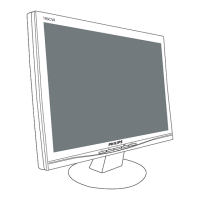
DELL P1230 M25P
Go to cover page
Fig. 5
Fig. 4
Fig. 3
Fig. 6
Fig. 8
Fig. 2
Fig. 7
screw
0. Location of the panel
1. General
Chassis :
Video panel :
Main panel :
Service position :
2. Repair instructions
0.1 Main panel (1160)
0.2 Video panel (1161)
To be able to perform measurements and repairs on the "circuit
boards", the monitor should be placed in Service Position (fig. 1) first:
Thereare2screwsinthelid[1screwareattherightsideofthe
monitor, The other 1 screw are at the left side of the monitor],to fix
the front cabinet and back cover of the monitor.
Step 1: To open the lid at the right-upper side and 1 right-
downer side of the monitor.(FIG.3)
Step 2: To open the lid at the left-upper side and left-
downer side of the monitor.(FIG.4)
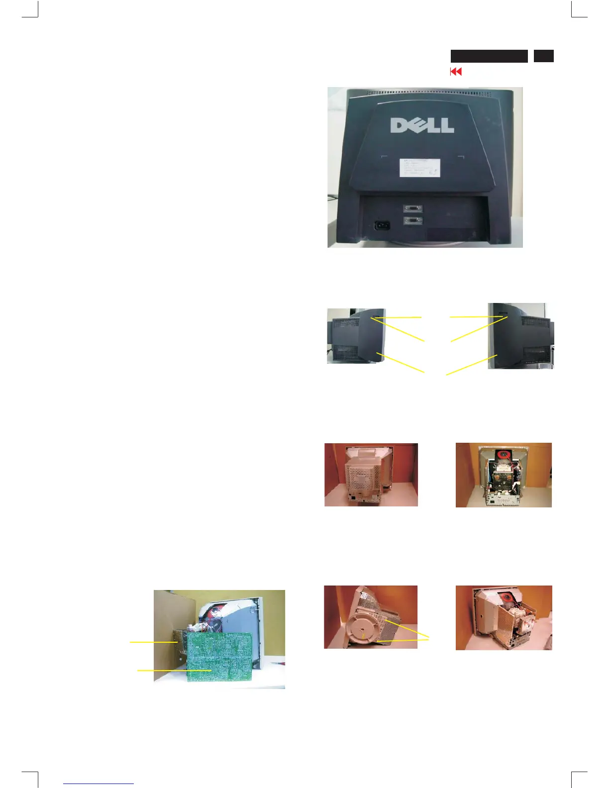
Step3: Toremovethebackcover,youcanseeFIG.5
Step4: Toremovethe13screwsonthemetalshield,andremove
themetalshield,youcanseeFIG.6.
-Afterremovethebackcover&metalshield,youcanseetheinside
of the monitor as Fig. 6.
-Toremove13 screwsforservicepositionasFig.5toFig.8.
-Includeremovebottomplatescrew,thenslideoutchassisboard
and disconnect metal shield.
- After remove the metal frame (Fig. 5), to remove the metal shield
on rear side of Video panel for measurement.
After remove the metal frame.
- To cut out cable tie and disconnect "video panel"
-TodisconnectEHTcable
- To disconnect ground wire(1703) of video board.
- To disconnect M1311(4pin) to control panel.
- To disconnect M1501(4pin) yoke connector.
- To disconnect M1131(2pin) degaussing coil
-ToslideoutMainpanelasFig.1.
TogetservicepositionasFig.1throughFig.2toFig.8.
Aftertheservicepositionwasobtained,allthepanel's coppertrack
side could be accessed.
Howtoremovethebackcoverofmonitor:
screw in
1screw in
Fig. 1 Service Position
1161
lids
screws
screws
1160