DISASSEMBLY AND ASSEMBLY OF DECK MECHANISM
4-9
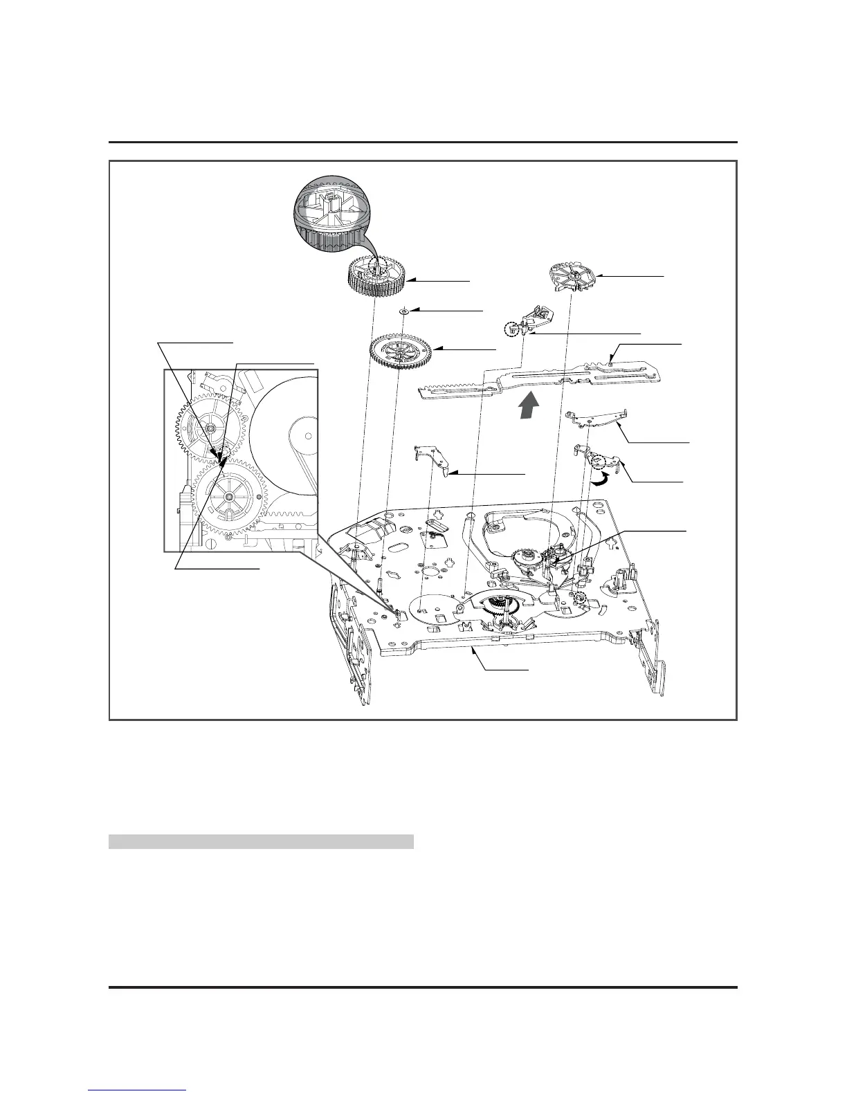
Gear Drive
Washer (W2)
Gear Cam
Plate Slider
Lever Tension
Lever spring
Base Loading
Gear Sector
(B)
(A)
(H10)
(W2)
(L2)
(H11)
Chassis
Gear Cam Hole(C)
Gear Cam Hole(B)
Gear Drive Hole(A)
Brake Assembly Capstan
Lever Brack
Fig. A-7
24. Gear Drive (Fig. A-7-1)/
Gear Cam (Fig. A-7-2)
1) Remove the washer (W2) and then disassemble the
gear drive.
2) Release the hook (H10) of the gear cam and then disas-
semble it upward.
CAUTIONS
For the assembly, adjust both the gear driver hole (A) and
the gear cam hole (B) straightly and then correspond the
gear cam hole (C) to the chassis hole.
25. Gear Sector (Fig. A-7-3)
1) Release the hook (H11) of the gear sector and then hold
the gear sector upward.
26. Brake Assembly Capstan (Fig. A-7-4)
1) Release the locking tab (L2) on the bottom side of the
plate slider and then disassemble it upward.
27. Plate Slider (Fig. A-7-5)
1) Disassemble the plate slider while holding it up.
28. Lever Tension (Fig. A-7-6)
1) Release the lever tension from the guide (A) of chassis
while turning it anti-clockwise.
2) Disassemble the lever tension while holding it up.
29. Lever Spring (Fig. A-7-7)
1) Release the (B) part of the lever spring from the guide
(A) of chassis while turning it anti-clockwise.
2) Disassemble the lever tension while holding it up.
30. Lever Brake (Fig. A-7-8)
1) Disassemble the lever brake while holding it up.
(Fig. A-7-4)
(Fig. A-7-5)
(Fig. A-7-8)
(Fig. A-7-7)
(Fig. A-7-6)
(Fig. A-7-1)
(Fig. A-7-2)
(Fig. A-7-3)