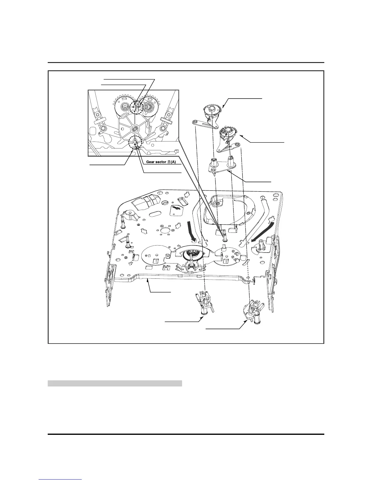
Fig. A-8
31. Gear Assembly P2 (Fig. A-8-1)/
Gear Assembly P3 (Fig. A-8-2)
1) Hold the gear assembly P2 upward.
2) Hold the gear assembly P3 upward.
CAUTIONS
For the assembly, check the holes of both the gear assem-
bly P2 and the P3 are adjusted straightly, and then corre-
spond the gear section groove (A) to the plate slider hole (B).
32. Base Assembly P2 (Fig. A-8-3)/
Base Assembly P3 (Fig. A-8-4)
1) Disassemble the base assembly P2 downward while mov-
ing it toward the arrow (A) direction along with the guide
hole of chassis.
2) Disassemble the base assembly P2 downward while mov-
ing it toward the arrow (B) direction along with the guide
hole of chassis.
33. Base Loading (Fig. A-8-5)
1) Release 3 hooks (H12, 13, 14) of the base loading, and
then disassemble them upward.
- Reverse the mechanism.
(Fig. A-8-1)
(Fig. A-8-2)
(Fig. A-8-5)
(Fig. A-8-4)
(Fig. A-8-3)