Mechanical Instructions
EN 18 EM5.1E4.
4.3.3 Component Side LSP
Figure 4-3 Service position 2
For better accessibility of the LSP, do the following (see figure
above):
1. Remove the LSP-bracket from the bottom tray by pulling it
backwards.
2. Hook the bracket in the first row of fixation holes of the
bottom tray. In other words, reposition the bracket from [1]
to [2].
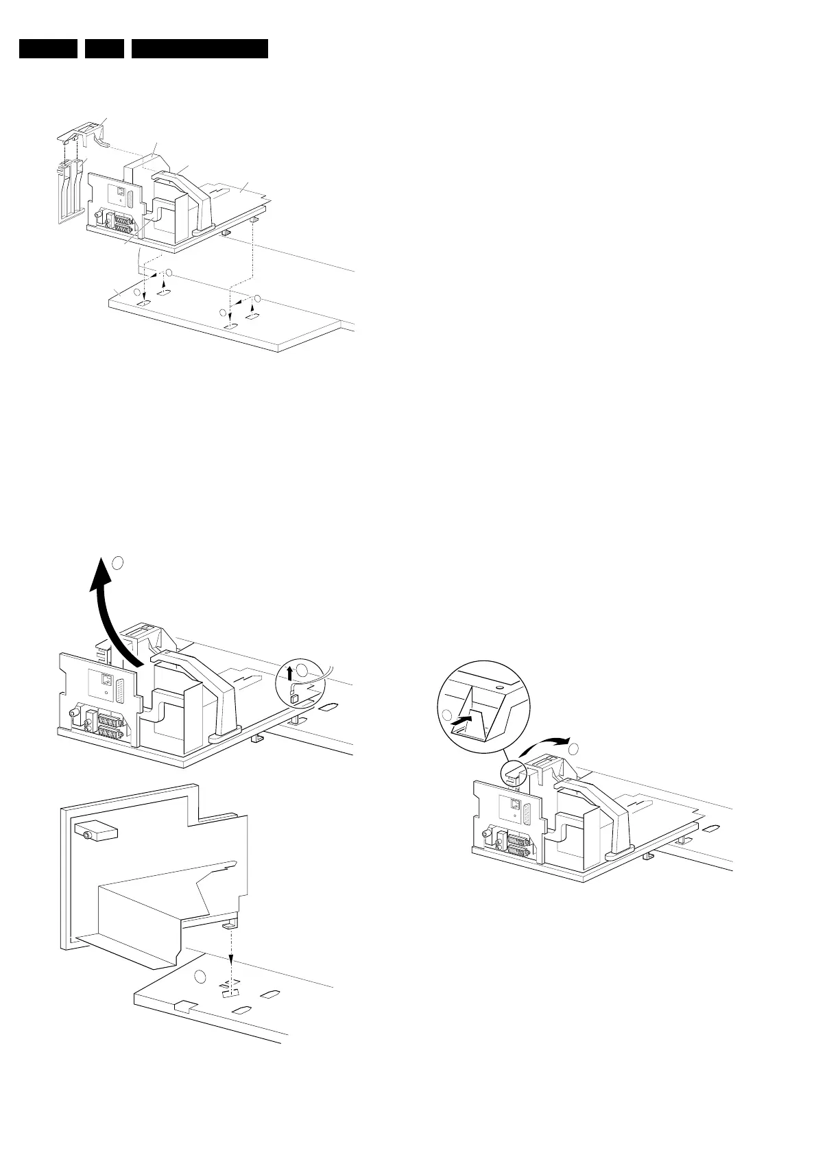
4.3.4 Solder Side LSP
Figure 4-4 Service position 3
To get access to the bottom side (solder side) of the LSP, do
the following (see figure above):
1. Unlock the DAF-module bracket (see paragraph 'DAF
Assy/Panel' further down).
2. Unlock the Double Window, PIP module (if present),
release the locking clip and pull the bracket out of the
locking holes in the bottom plate.
3. Disconnect the degaussing coil connector 1502 [1] from
the LSP.
4. Release the high voltage cable out of its guiding clamp.
5. Release the wiring from their fixation clamps, in order to
position the LSP in the service position.
6. Some cables should be led underneath the CRT panel
instead of above this panel.
7. Move the LSP to the left, at the same time rotate the panel
90 degrees clockwise [2] and next, place it upright at the
left side of the bottom tray [3].
8. Put the panel with the right sided locking hook in the
oblique accessed mounting hole in the bottom plate and
pull it backwards to lock the panel in this position.
4.3.5 Small Signal Board (SSB)
Caution:
Always switch the set completely ‘OFF’ (disconnect the mains
cord) before you remove or replace the SBB.
As the 5V2 standby voltage is always present (while the set is
switched ‘On’, in ‘Standby’ or in ‘Protection’ mode) on the
SIMM connector, it is very risky to remove the SSB in this
situation, because the risk of short circuiting is very great.
In fact, there is no predefined service position for the SSB. Most
test points are located on the A-side (side that is facing the
tuner). If you have to replace ICs, you must take the complete
SSB module out of the SIMM-connector.
Note: For good access to the A-side, it is necessary to remove
the Auto-Scavem assy (at the left side of the SSB). See
description in paragraph ‘Assy/Panel removal' to remove the
Auto-Scavem panel/bracket.
To get access to the SSB test points, do the following:
Figure 4-5 SSB removal (part 1)
1. Put the LSP in service position 2 (as described above).
2. Release the two clamps at the top of the SSB bracket [2]
and pull the bracket upward (it hinges in the bracket at the
LOT side).
3. Now you can remove the complete SSB bracket.
CL 26532041_065.eps
110402
LOT - bracket
SSB
LSP
Bottom tray
SSB top-bracket
CONNECTOR SUPPORT
bracket
AUTO-SCAVEM
bracket
2
1
1
2
CL 26532041_066.eps
110402
3
1502
1
2
CL 26532041_067.eps
110402
2
1