Mechanical Instructions
EN 19EM5.1E 4.
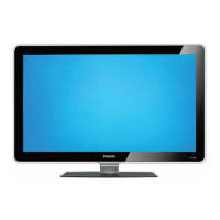
Figure 4-6 SSB removal (part 2)
1. Push the top of the SSB towards the LOT [1].
2. Due to the pressure, the two metal clamps at both sides of
the SIMM-connector will release [2].
3. Take the complete SSB out [3].
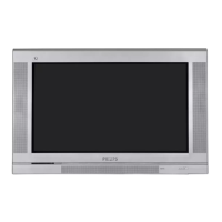
Figure 4-7 SSB removal (part 3)
1. Once you have taken out the SSB, remove the shieldings
[2]. Sometimes it is necessary to unsolder some solder-
tags first [1].
2. Now re-place the SSB module in the SIMM-connector in
reverse order.
Notes:
For better access to the SSB, it is possible to order an
'extension tool' with cables. You can use this service extension
tool to connect a Small Signal Board (SSB) of an A10 or EMG
(EMx) chassis, via 2 “IDE” cables to the SIMM connector in the
set. In this way, you can service the SSB more easily outside
the TV set. You can order this tool under 12nc: 9965 000
14526.
4.4 Assy / Board Removal
Sometimes, it can be necessary to swap a complete assy or
Printed Wiring Board (PWB). How that can be done is
explained below.
4.4.1 Top Control Assy/Panel
Figure 4-8 Top control assy
1. Release both fixation screws about 5 full turns.
2. Pull the complete assy back- and upwards (it hinges in the
cabinet front).
3. Flip the assy, and you can access the board by releasing
(carefully) the four fixation clamps.
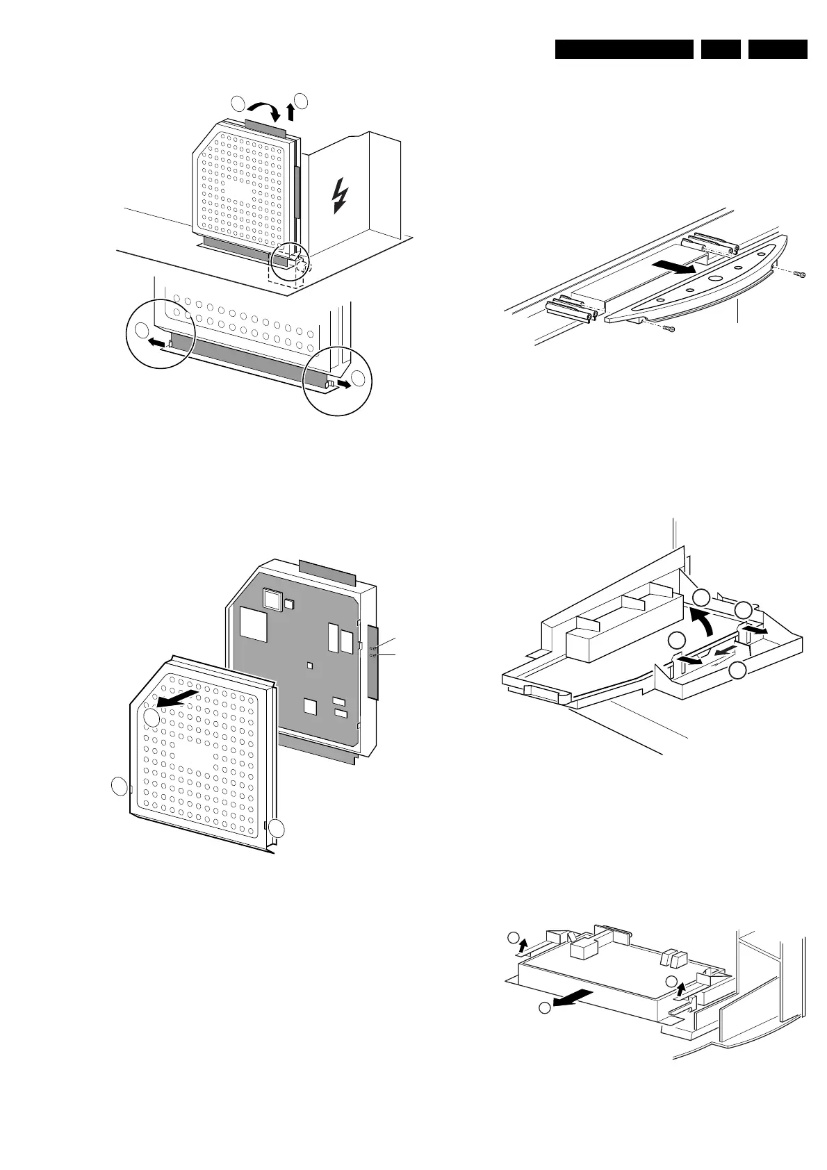
4.4.2 Side-I/O Assy and Panel
Figure 4-9 Side I/O assy
1. Release the snap-hook [1] with your finger.
2. At the same time, pull the assy backwards [2].
3. Release the two fixation clamps on the right side of the
bracket (the I/O board hinges at the left side).
4. Remove the board from the bracket.
4.4.3 Mains Switch Assy/Panel
Figure 4-10 Mains Switch Assy
1
2
3
CL 26532041_068.eps
110402
2
SSB
CL 26532041_069.eps
110402
1
1
SDM
SAM
SSB
2
CL 16532149_068.eps
051201
Top control board
CL 16532149_069.eps
061201
1
3
2
2
CL 16532149_070.eps
061201
1
2
1