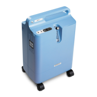
Page 29 E
VERFLO
TM
SERVICE & TECHNICAL INFORMATION 1039055, VER. 06
ASSEMBLY INSTRUCTIONS FOR EQUIPMENT OPTION 3
Option 3 is only available in SCMS (equipment not shown above).
1. Attach the TSI flow meter to the inlet filter.
2. Attach the grommet to the inlet adapter.
3. Inset the pipe nipple into a length of hose. (@ 7” in length)
4. Attach the hose to the Compact Plastic Needle Valve 3/8" Barb X 3/8" Barb Connections.
5. Join a short length of hose to the white polypropylene barbed tube.
6. Connect the pressure gage to the tee fitting on the barbed tube.
7. Attach a length of blue hose (30” in length) from the barb fitting to a brass fitting.
This is the test end of the device for testing the compressors for flow and pressure.
8. Insert an inline muffler to help collect any sieve material in the test line.
9. Use clamps to secure the fittings together.
PROCEDURE
1. Follow the procedures detailed in the EverFlo Service Manual for the removal of the following
components:
a. Filter Cover
b. Inlet Filter
c. Rear Cabinet

 Loading...