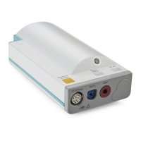
Sidestream CO
2
Measurement
Introduction to the Instrument
51
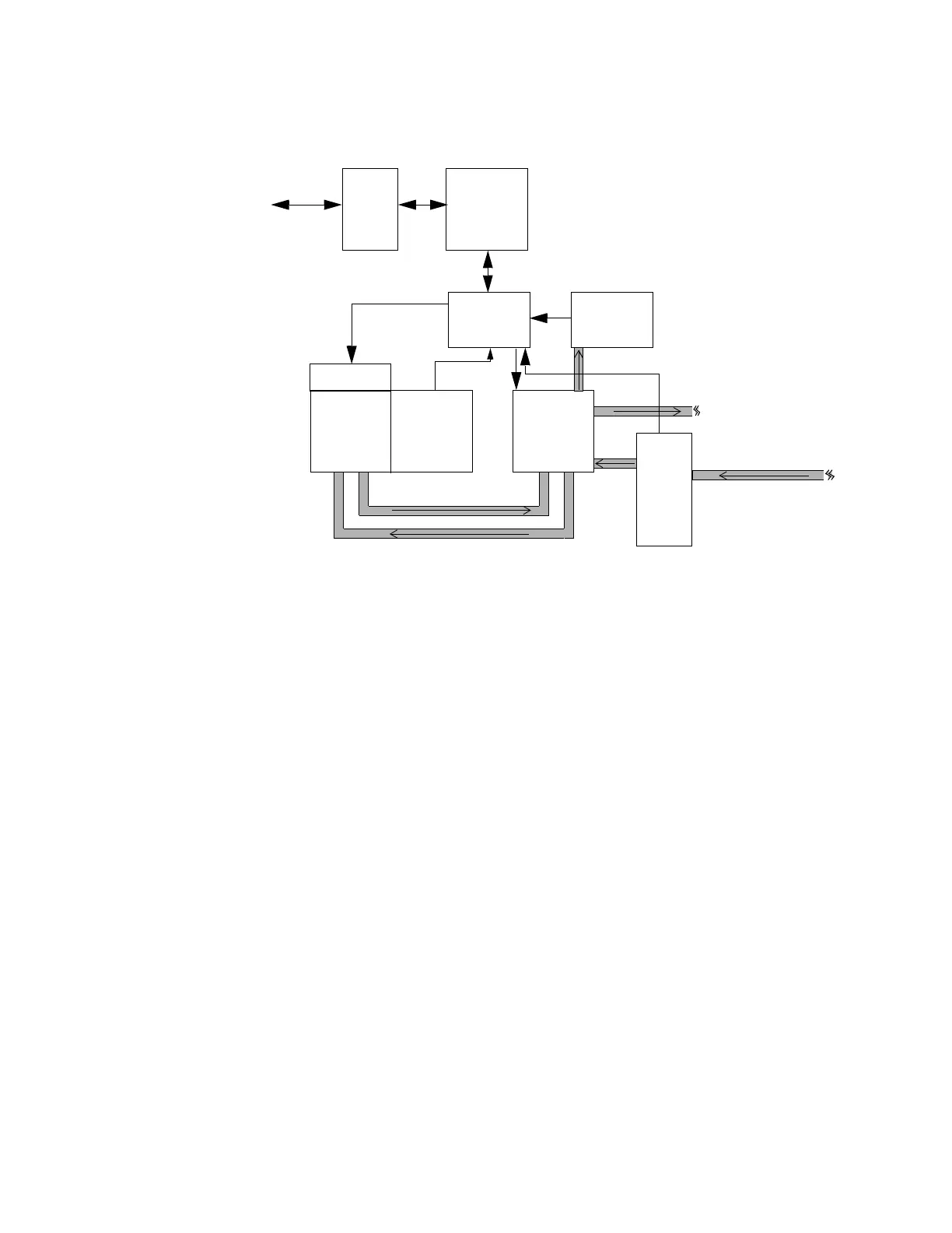
Block Diagram of the Sidestream CO
2
measurement
Theory of Operation for M3015A Sidestream CO
2
Sidestream CO
2
is measured based on non-dispersive infrared absorption of breathing gas
samples. Signals progress through the circuit as follows:
Flow System
The flow system circulates the sidestream gas sample and pumps out waste gas.
Temperature Sensor
The temperature of the detector is measured and used to compensate temperature drift of the
CO
2
reading. Signals from the temperature sensor in the detector are amplified and then
passed through an Analog-to-Digital converter.
Exciter and Infrared Source
The exciter generates a high frequency, high voltage signal to ignite the infra-red source and
to generate the infrared radiation needed to measure the CO
2
concentration in the
measurement cell.
Gas Inlet
with
Optical
Code
Recog-
nition
Serial
interface
with
Exciter
IR
Source
Detectors
and
Temp Sensor
Flow System
Pump,
solenoid,
tubing
Controller
and
Peripherals
Analog
Section
Pressure
Sensor
Gas Outlet
Sample Line Inlet
to/from Server
Exciter
IR
Source