EasyManua.ls Logo

Philips MC77 User Manual

Philips MC77
79 pages
To Next Page IconTo Next Page
Page #1 background imageLoading...
Page #1 background image
Technical specification . . . . . . . . . . . . . . . . . . . . . . . . . . . 1-2
Measurement setup . . . . . . . . . . . . . . . . . . . . . . . . . . . . . 1-3
Warnings & Safety . . . . . . . . . . . . . . . . . . . . . . . . . . . . . . 1-4
Service Hints . . . . . . . . . . . . . . . . . . . . . . . . . . . . . . . . . . 2-1
Location of printed circuit boards . . . . . . . . . . . . . . . . . . . 2-2
Brief Operating Instructions
Dismantling Instructions . . . . . . . . . . . . . . . . . . . . . . . . . . 3-1
Service Testprogram . . . . . . . . . . . . . . . . . . . . . . . . . . . . 3-4
Wiring Diagram. . . . . . . . . . . . . . . . . . . . . . . . . . . . . . . . . 4-1
Blockdiagram . . . . . . . . . . . . . . . . . . . . . . . . . . . . . . . . . . 5-1
Published by HB 0218 Service Audio Printed in The Netherlands Subject to modification
©3103 785 25160
CDR Mini System
CLASS 1
LASER PRODUCT
©
Copyright 2002 Philips Consumer Electronics B.V. Eindhoven, The Netherlands
All rights reserved. No part of this publication may be reproduced, stored in a retrieval
system or transmitted, in any form or by any means, electronic, mechanical, photocopying,
or otherwise without the prior permission of Philips.
Table of Contents
MC-77/21/21M/22/37
Front Display Board . . . . . . . . . . . . . . . . . . . . . . . . . . . . . 6
Tuner Board . . . . . . . . . . . . . . . . . . . . . . . . . . . . . . . . . . . . 7
Front Control Board . . . . . . . . . . . . . . . . . . . . . . . . . . . . . 8
STANDBY (POWER) PART . . . . . . . . . . . . . . . . . . . . . . . . . . . . . . . 8-1
KEY CONTROL (KEYB. 1) & LIGHTWASH PARTS . . . . . . . . . . . . . . . 8-2
HEADPHONE, JOG (VOLUME) AND CDC KEY PARTS . . . . . . . . . . . . 8-3
Electronic Tape Function ETF8 . . . . . . . . . . . . . . . . . . . . 9
3 Disc Tray Changer Module . . . . . . . . . . . . . . . . . . . . . 10
Power Module . . . . . . . . . . . . . . . . . . . . . . . . . . . . . . . . . 11
Exploded view of set . . . . . . . . . . . . . . . . . . . . . . . . . . . . . 12
Partslist of set . . . . . . . . . . . . . . . . . . . . . . . . . . . . . . . . . . 12
www.freeservicemanuals.info
11/03/2012
www.nostatech.nl
World of free manuals

Table of Contents

Other manuals for Philips MC77

Question and Answer IconNeed help?

Do you have a question about the Philips MC77 and is the answer not in the manual?

Philips MC77 Specifications

General IconGeneral
BrandPhilips
ModelMC77
CategoryCD Player
LanguageEnglish

Summary

Technical Specification

Measurement Setup

Diagrams illustrating measurement procedures for various system components.

Warnings & Safety

Essential safety precautions and warnings for handling the device and ESD protection.

Service Hints

Location of Printed Circuit Boards

Visual diagram showing the placement of various PCBs within the system.

Brief Operating Instruction

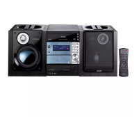
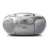
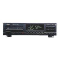
A concise overview of the system's basic operation and features.

Controls

Detailed description of system controls and remote control functions.

Preparations

Instructions for connecting power, antennas, speakers, and inserting batteries.

Technical Remarks

General technical notes and observations related to the system.

Dismantling Instructions

Set Block Diagram

Wiring Diagram

Front Display Board

ECO6 Tuner Board

Tuner Adjustment Table

Table detailing alignment procedures and settings for tuner adjustments.

Electrical Parts List - ECO6 Systems Non-Cenelec

Comprehensive list of electrical components for the ECO6 Tuner Board.

TUNER BOARD ECO6 Systems Cenelec

TUNER ADJUSTMENT TABLE

Table detailing alignment procedures and settings for tuner adjustments.

ELECTRICAL PARTSLIST ECO6 SYSTEMS-CENELEC

Comprehensive list of electrical components for the ECO6 Tuner Board.

Front Control Board

Standby (Power) Part - Circuit & Layouts

Circuit and layout for the power supply and standby functions.

Key Control (KEYB. 1) Part - Circuit & Layout Diagrams

Circuit and layout for the key control buttons and interface.

Lightwash Part - Circuit & Layout Diagrams

Circuit and layout for the lightwash illumination components.

Headphone Part - Circuit & Layout Diagrams

Circuit and layout for the headphone jack and related circuitry.

Jog (Volume) Part - Circuit & Layout Diagrams

Circuit and layout for the jog dial and volume control.

CDC Key Part - Circuit & Layout Diagrams

Circuit and layout for the CD control buttons.

Electrical Parts List - Front Control Board

ETF-8 Module

Tape Deck Wiring

Wiring diagram for the tape deck and its connection to the ETF8 board.

Tape Mechanism Electronics

Electronic schematic for the tape mechanism, including motor and switches.

Tape Adjustment & Check Table

Table for adjusting and checking tape playback performance parameters.

HEF4094BT Functional Block Diagram

Block diagram of the HEF4094BT shift register IC used in tape control.

Component Layout

Physical layout of components on the ETF8 board.

Chip Layout

Physical layout of chip components on the ETF8 board.

Electrical Parts List - ETF8 Board

List of electrical parts for the ETF8 board.

Autoreverse (AR) Tape Mechanism

Mechanical Parts List - Autoreverse Tape Mechanism

List of mechanical parts for the autoreverse tape mechanism.

Non-Autoreverse (NAR) Tape Mechanism

Mechanical Parts List - Non-Autoreverse Tape Mechanism

List of mechanical parts for the non-autoreverse tape mechanism.

Tape Module Exploded View

Electrical Parts List - ETF8 Board

Electrical Parts List - ETF8 Board

3DTC Module (Basic version)

Warning

Wiring Module

Wiring CD Drive

Wiring details for the CD drive laser unit and motors.

Location of switches

Block Diagram 3DTC

Mainboard Componentside view

Component layout on the main board of the 3DTC module.

Mainboard Copperside view

Copper trace layout on the main board of the 3DTC module.

3DTC-mainboard part 2

Schematic diagram part 2 for the 3DTC main board.

3DTC-mainboard part 3

Schematic diagram part 3 for the 3DTC main board.

3Disc Tray Changer Exploded view

Mechanical Parts

List of mechanical parts for the 3-disc tray changer.

Power 2002 Module (70W Class D)

Combi Board

Table of contents for the Combi Board section.

Mains Board

Table of contents for the Mains Board section.

Class-D Circuit Description

Service Hints

Class-D Circuit Description

Service Hints

Service Hints

Power 2002 70W Class D Combi Board Circuit Diagram Overview

Source Selector Part

Section detailing the source selection IC and its related circuitry.

Oscillator & Pre-Amplifier Part

Section covering the oscillator and pre-amplifier stages.

Amplifier Part Left Channel

Section detailing the left channel amplifier circuitry.

Amplifier Part Right Channel

Section detailing the right channel amplifier circuitry.

Audio Frequency & Logic Part

Section covering headphone amplifier, subwoofer out, and logic controls.

Source Selector Part

Audio Frequency & Logic Part

Supply, Oscillator & Pre-Amplifier Part

Amplifier Part Left Channel

Amplifier Part Right Channel

Combi Board Copperside view

Combi Board componentside view

Mains Board Copperside view

P2002 70W CLASS D MAINS

Electrical Parts List Power 2002 70W Class-D Combi Board

EXPLODED VIEW - MC-77

Mechanical Parts

List of mechanical parts for the MC-77 system.

EXPLODED VIEW - Front

Mechanical Parts

List of mechanical parts for the front assembly.

MISCELLANEOUS

Related product manuals