3-2
3-2
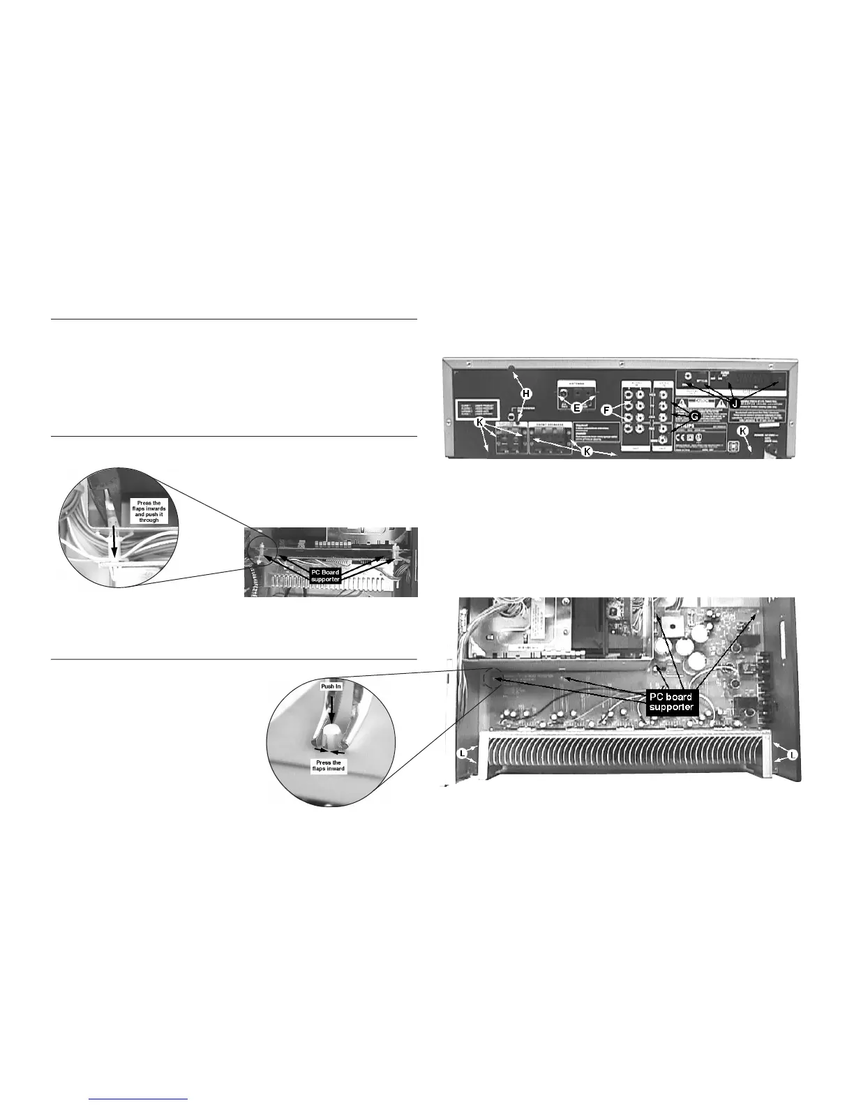
1) Loosen 2 screws E on the Rear panel to remove the Tuner
Board.
2) Loosen 2 screws F on the Rear panel to remove the Audio
Switch Board.
3) Loosen 3 screws G on the Rear panel to remove the Video
Switch Board.
Dismantling the Tuner, Audio Switch, Video Switch, Pro-Logic and AV Board (Refer figure 8)
4) Loosen 3 screws H to remove the Pro-Logic Board.
- 2 screws on the Rear panel
- 1 screw (including metal mounting bracket) on the
inside of the set as shown in figure 5.
5) Loosen 4 screws J on the Rear panel to remove the AV
Output Board.
1) Release 4 catches of the pc board supporter with a long
nose plier as shown in figure 7.
Dismantling the Regulator Board
Figure 7
Dismantling the Power Amplifier Board
1) With the set upside down, release 5 catches of the pc
board supporter with a long-nose plier as shown in figure
9.
2) With the set upright again, remove the Pro-Logic Board as
describe above.
3) Loosen 4 screws L mounting the heatsink to the bottom
plate as shown in figure 9.
4) Loosen 7 screws K on the Rear Panel (see figure 8)
- 4 screws for the Speaker sockets
- 3 screws to detach the Rear Panel from the bottom
plate.
Figure 9
Figure 8