OPERATION AND
APPLICATION
GENERAL INFORMATION
This
section
outlines
the procedures
and
precautions necessary
for
operation. It identifies and briefly
describes the functions
of the front
panel
controls and indicators,
and explains
the
practical aspects of
operation to enable
an
operator to
evaluate
quickly the instrument's
main functions.
SWITCHING
ON THE INSTRUMENT
After
the
instrument has been
connected to
the mains voltage in
accordance with
clauses 2.2.4 and
2.3,
it can
be switched
on by
depressing
the mains switch POWER. The white spot
inside the POWER switch
mechanically
indicates that the
instrument is
switched on.
Having
switched on
the instrument, it is
immediately ready for
use. With normal installation
in accor-
dance with Section 2.4 and after a
warming-up time of 5 minutes, the characteristics
specified in Section
1 .2 are valid.
After switching power off,
a time
interval! of at least
5
s should pass
by -allowing the capacitors of the
power supply to discharge- before the device is
switched
on
again.
This procedure is necessary
to set the
internal logic circuitry
to
its correct initial condition.
WARNING: Before
switching on, ensure that the instrument has been installed
in accordance with the
instructions mentioned in
Section
2.
SELFTEST ROUTINE
Immediately
after power being switched on a seiftest routine is performed,
whereby several functions
are tested. For check
of
the display all segments
of the
decimal
and dimension indications,
decimal
points and equivalent-circuit
symbols
are shown for 3 seconds.
After this
a
possible
error
will
be indicated by the
display
readings EQ ... E3. The
equivalent-circuit sym-
bols are not
shown. The
error codes are pointing towards the following failures.
EO
El
E2
E3
RAM test, microprocessor
s
measuring ranges
ahalog/digital converter
reference measurement
Further error indications
are explained in
chapter
3.4.6.
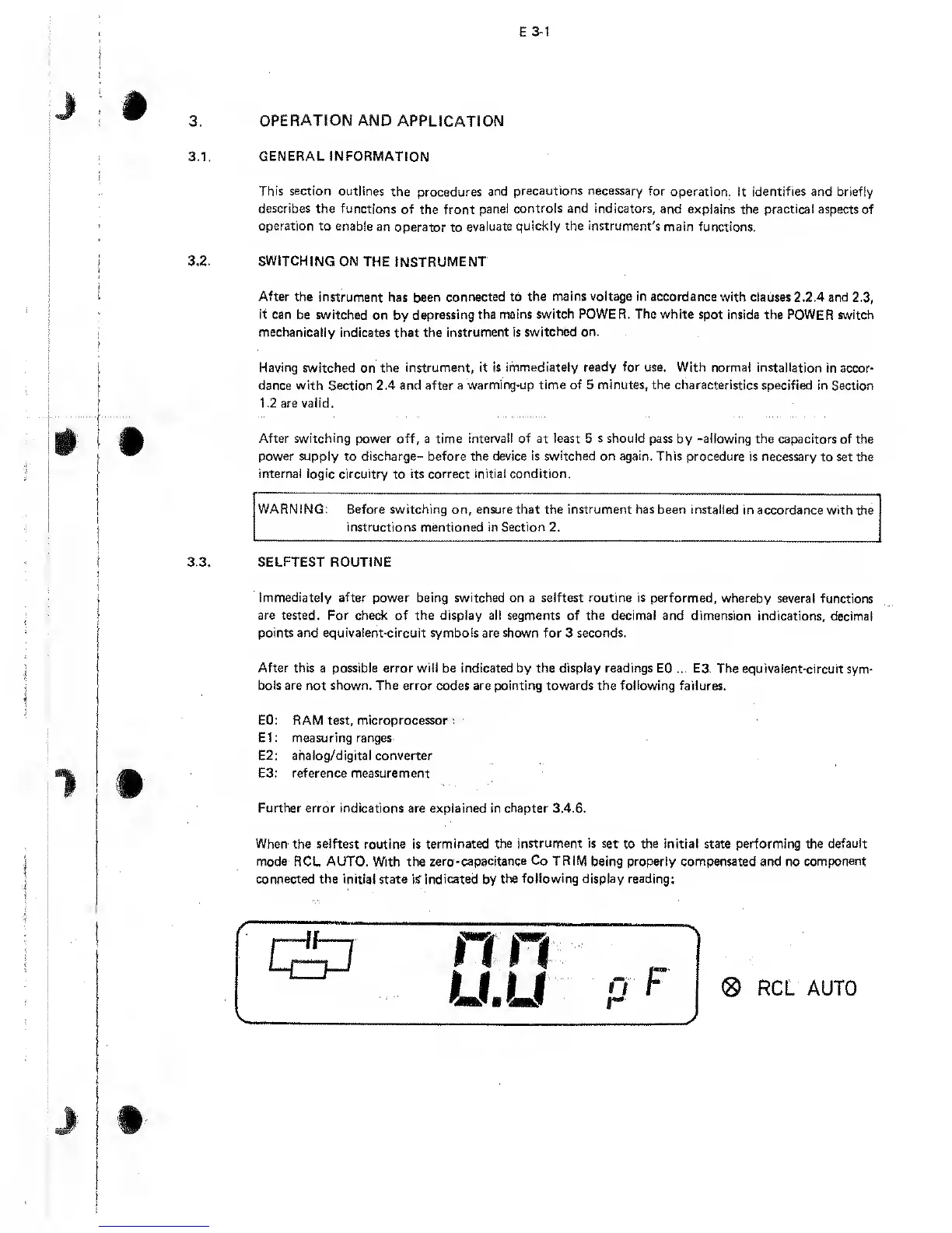
When the seiftest routine is terminated
the instrument is set
to the initial state
performing
the
default
mode RCL AUTO.
With
the zero
-capacitance Co TRIM
being properly compensated and no
component
connected the initial
state is
indicated
by
the
following
display reading:
®
RCL AUTO