E
1-1
1. GENERAL
1.1.
INTRODUCTION
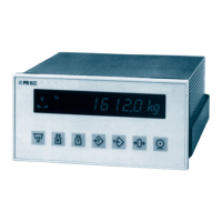
The
PM
6303
RCL meter is used
for
measurements of resistances,
capacitances and inductances. Pro-
viding
auto-function and
auto-ranging facility
the instrument
allows fast and
high
precision
measure-
ments of passive components over a
wide range.
The component
under test
is directly
connected to the
instrument,
either
via a two-terminal test fix-
ture, a four-wire
test cable
or a four-terminal
test adapter. The measurement
result, namely numerical
value, dimension
and
the
equivalent-circuit
symbol, is immediately
displayed
on a large
4-digit
liquid-
crystal display
(LCDi,
updated
at a rate of two
measurements per second.
A microprocessor
controls
the measurement process, computates the measurement
value
and transfers
the result to the display.
In
the RCL
AUTO mode
the dominant component, either R,
C
or L of the
component under
test
is
automatically selected for display. RCL AUTO is
also the default mode of
the instrument
after power-
on.
For
an inductance e.g. with quality factor 500 >
Q
> 1
the instruments indicates
the measurement
value of the
series inductance and as
equivalent-circuit symbol the series
connection of
a
resistance
and an inductance.
In addition to the RCL
AUTO mode with display
of
the
dominating
component
8
further
parameters
can be selected
by
2
pushbuttons providing a
stepping function, whereby
the appropriate parameter
is marked
by a LED:
Quality factor
Q,
dissipation factor
D,
parallel resistance
Rp^
series resistance Rs,
impedance Z,
...
!
parallel capacitance
Cp or
parallel inductance
Lp,
series capacitance Cs or series inductance Ls,
series
capacitance, internally biased Cs
(2
V BIAS)*
The instrument is especially suited for
use in iaboratories, for quality control, service
workshops and
for
education purposes.-?
-
-
1.2.
t
"
CHARACTERISTICS
^7"'^
'T.'
1 .2 .
1. Sa
f
ety
characteriiistic*£
*
y
^
''
'•
^
"
This
apparatus has been designed and tested
in
accordance with Safety Class
I
requirements of 1EC
Publication
348,
Safety Requirements for
Electronic Measuring Apparatus,
and has been supplied in
a safe condition* This manual contains some information and warnings which must
be followed by
the
user
to
ensure safe operation and to retain the apparatus in a safe condition.
1.2.2. Performance
characteristics,
specifications
Properties
expressed in
numerical
values with stated
tolerance
are guaranteed by the
manufacturer.
Specified non-toierance numerical values indicate those that could be nominally expected
from the
mean
of a
range
of identical
instruments.
This
specification
is valid
after the instrument has warmed up
for
5
minutes (reference
temperature
23°c)^x.
:t;
'-'•
If
not
stated otherwise, relative or absolute
tolerances
relate
to
the set value.