Mechanical Instructions
EN 24 Q552.2L LA4.
2012-Mar-16
back to
div. table
4.5.8 LCD Panel
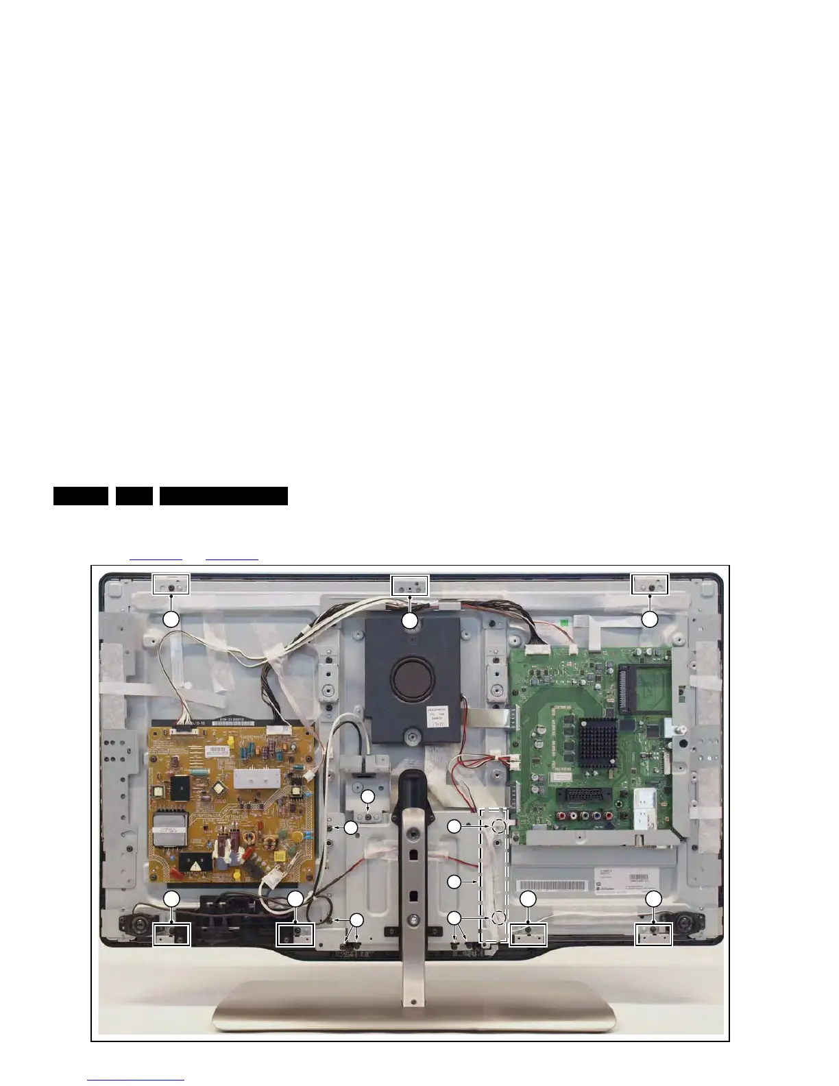
Refer to Figure 4-31
and Figure 4-32 for details.
Figure 4-31 LCD panel [1/2]
1. Remove the SSB as described earlier.
2. Remove the PSU as described earlier.
3. Remove the tweeters with their subframes and subwoofer
as described earlier.
4. Remove the stand and -support as described earlier.
5. Remove the cables [1].
6. Remove the stand subframe [2].
7. Remove the mains switch subframe [3].
8. Remove the Ambilight units together with their subframes
as described earlier.
9. Unplug the connector from the keyboard control-, and IR &
LED board as described earlier.
10. Remove all remaining cables and subframes.
11. Use a screwdriver to release the clamps [4] that secure the
panel and take the panel out.
Remove the clamps from the panel before sending the panel in
for Service.
Figure 4-32 LCD panel [2/2]
4.6 Set Re-assembly
To re-assemble the whole set, execute all processes in reverse
order.
Notes:
• While re-assembling, make sure that all cables are placed
and connected in their original position.
• Pay special attention not to damage the EMC foams in the
set. Ensure that EMC foams are mounted correctly.