Circuit Descriptions
EN 55Q552.2L LA 7.
2012-Mar-16
back to
div. table
7.2 Power Supply
7.2.1 Connector Overview, Block Diagram and Fault Finding
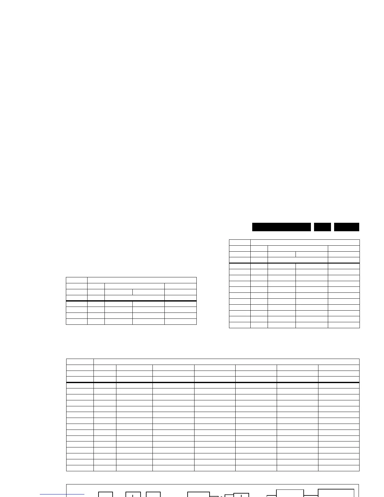
Table 7-1 Connector overview non-Ambilight sets
Table 7-2 Connector overview Ambilight sets
(xxPFL8xxx sets)
Note: * optional
Figure 7-3 Block diagram
Connector
no. 1308 1316 - 1319 1M95
Descr. Mains Display Description PSU to SSB
Pin CN1 CN2 - CN3 CN4
1 N Anode 1+ LED input 3V3stdby
2 L n.c. - Standby
3 - Cathode 1- LED output GND1
4 - n.c. - GND1
5 - Anode 2+ LED input +12V
6 - n.c. - +12V
7 - Cathode 2- LED output +Vsnd
8 - n.c. - * GND_SND
9 - Anode 3+ LED input * BL-ON-OFF
10 - n.c. - * BL-DIM1(Vsync)
11 - Cathode 3- LED output * BL-I-CTRL
12 - n.c. - * POK
13 - Anode 4+ LED input * +24V (AL2_DVBS)
14 - n.c. - * GND1
15 - Cathode 4- LED output * -
Connector
no. 1308 1316 - 1319 1M95
Descr. Mains Display Description PSU to SSB
Pin CN1 CN2 - CN3 CN4
Connector
no. 1308 1316 1319 1M95 1M99 1M09 1MP1
Descr. Mains Display Display PSU to SSB PSU to SSB * Ambilight TCON (for > 46" only)
Pin CN1 CN2 CN3 CN4 CN5 CN6 CN7
1 N Anode L1 Anode R2 3V3stdby GND_AL GND_AL +12V/24V
2 L n.c. n.c. Standby +12V_AL +12V_AL +12V/24V
3 - L1 Cathode R8 Cathode GND1 GND_AL GND_AL n.c.
4 - L2 Cathode R7 Cathode GND1 +12V_AL +12V_AL GND1
5 - L3 Cathode R6 Cathode +12V GND_AL - GND1
6 - L4 Cathode R5 Cathode +12V +12V_AL - -
7 - n.c. R4 Cathode +Vsnd 2D/3D - -
8 - L5 Cathode R3 Cathode GND_SND GND1 - -
9 - L6 Cathode R2 Cathode BL-ON-OFF +12V - -
10 - L7 Cathode R1 Cathode BL-DIM1(Vsync) BL-SPI-SDO_BL-DIM2 - -
11 - L8 Cathode n.c. BL-I-CTRL BL-SPI-CSn_BL-DIM3 - -
12 - n.c. Anode R1 POK BL-SPI-CLK_BL-DIM4 - -
13 - Anode L2 - +24V (AL2_DVBS) MAINS-OK / TEMP - -
14 - - - GND1 - - -
15-------
19132_012_111221.eps
111221
V
STB
Regulator
V
SSB
BL Driver 1
BL Driver 2
Back Light
V
SND
STBY
ACin
198 V - 264 V
90 V - 276 V
Line
filter
Resonant
converter
PFC
Diode
bridge