Circuit Descriptions
EN 59Q552.2L LA 7.
2012-Mar-16
back to
div. table
Figure 7-10 Ambilight configuration
The Ambilight implementation consists of 2 separate units in
the set, where the Ambilight module located on the right (seen
from the back of the set) acts as a Master and the module on
the left acts as a Slave.
The NVM is located on the Master Ambilight module. This
module communicates via the SPI communication protocol
with the CPLD located on the SSB whereas the Slave Ambilight
module communicates via the PWM communication protocol
with the Master Ambilight module.
The supply voltage of the modules is +24 V.
Refer to Figure 7-11
and Figure 7-12 for the Ambilight board
implementation.
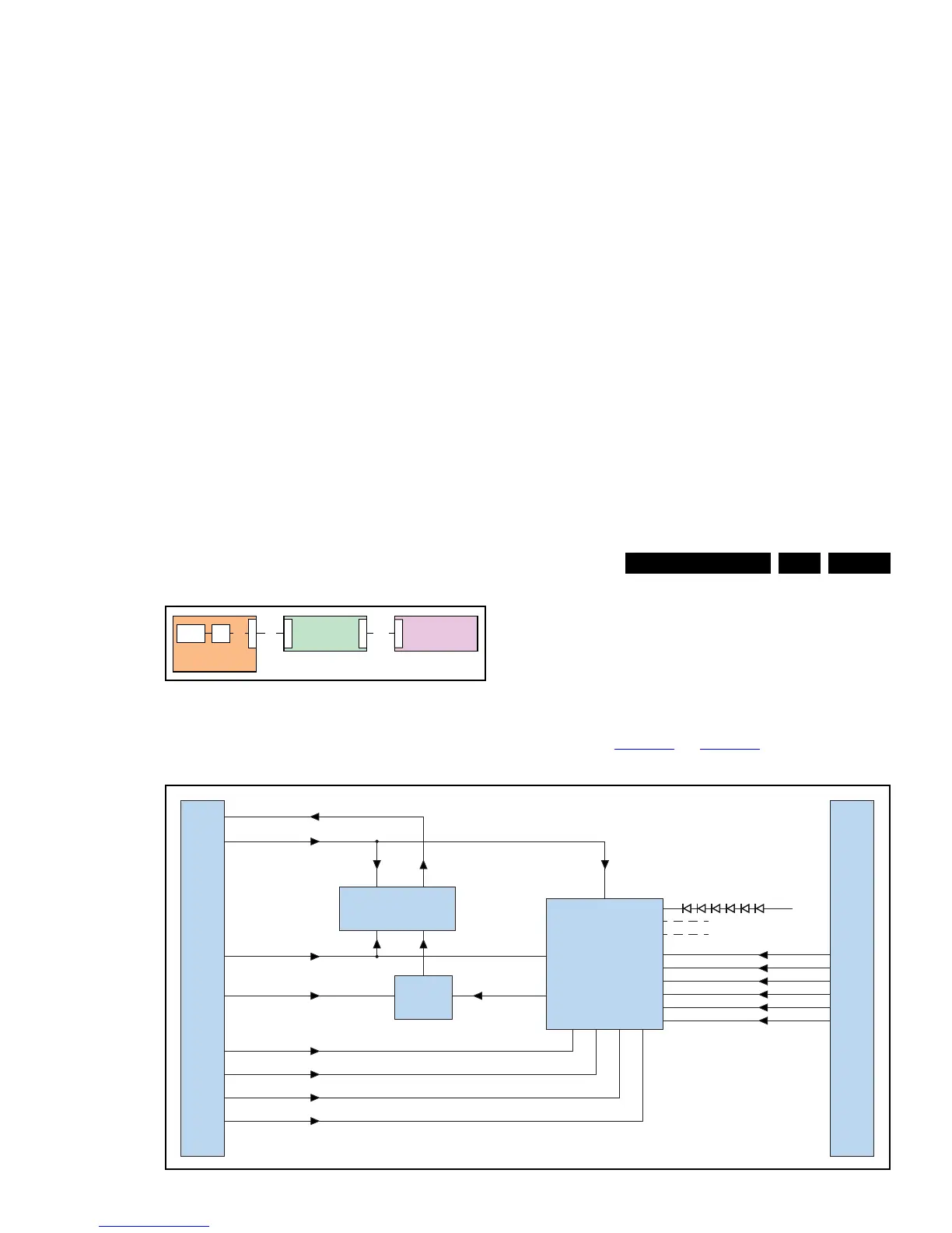
Figure 7-11 Master Ambilight module
Figure 7-12 Slave Ambilight module