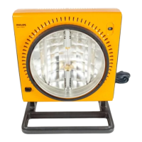
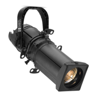
User’s Manual PL House Light MKII LED Luminaires
10 INSTALLATION AND SET UP
Step 4. Make electrical connections from power source at J-Box according to your market as follows:
a. For 120VAC Markets ONLY:
1) Remove cover from Junction (J) Box.
2) At J-Box, connect AC input wiring as illustrated in Figure 6. Refer to "Power Requirements" on
page 7 for power requirements.
Figure 6: J-Box Electrical Connections - 120VAC Markets
b. Connecting Power for Markets Other Than 120VAC Markets:
1) Remove cover from Junction (J) Box.
2) At J-Box, remove the Thermal Protective Switch as shown in Figure 7 and discard. It will not be
used.
3) Install supplied metal plug into Thermal Protective Switch hole.
4) Connect AC input wiring as illustrated in Figure 7. Refer to "Power Requirements" on page 7 for
power requirements.
Figure 7: J-Box Electrical Connections - Other Than 120VAC Markets
Step 5. Make any DMX512 control wiring connections as desired. Refer to "Connecting to the DMX512 Network"
on page 7 for more information.
Note: When using luminaire on a DMX512 network, the unit must be addressed via the on-board menu system.
Refer to "LCD Menu System" on page 13 for DMX addressing. The menu system may be accessed anytime the trim
ring / reflector assembly is removed.
Black (Main / Hot)
Light Blue (Main / Hot)
White (Neutral)
White
(Neutral)
Dark Blue
(Neutral)
Green (Earth / Ground)
Green/Yellow (Earth / Ground)
Thermal Protective Switch
Brown
(Main
/ Hot)
Bare Copper (Unit
Chassis Ground)
J-Box
Connecting to 120VAC Power (North American Markets)
From AC Supply
To F i x t ure
Brown (Main / Hot)
Blue (Neutral)
Green/Yellow (Earth / Ground)
Brown
(Main / Hot)
Dark Blue (Neutral)
Green/Yellow (Earth / Ground)
Bare Copper (Unit
Chassis Ground)
J-Box
Connecting to Power Other Than 120VAC
From AC Supply
To F i x t u r e