TDA8950_2 © NXP B.V. 2009. All rights reserved.
Product data sheet Rev. 02 — 11 June 2009 21 of 39
NXP Semiconductors
TDA8950
2 × 150 W class-D power amplifier
The most effective way to avoid pumping effects is to connect the TDA8950 in a mono
full-bridge configuration. In the case of stereo single-ended applications, it is advised to
connect the inputs in anti-phase (see Section 8.4). The power supply can also be
adapted; for example, by increasing the values of the supply line decoupling capacitors.
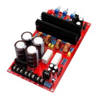
13.7 Application schematic
Notes on the application schematic:
• Connect a solid ground plane around the switching amplifier to avoid emissions
• Place 100 nF capacitors as close as possible to the TDA8950 power supply pins
• Connect the heatsink to the ground plane or to VSSPn using a 100 nF capacitor
• Use a thermally conductive, electrically non-conductive, Sil-Pad between the
TDA8950 heat spreader and the external heatsink
• The heat spreader of the TDA8950 is internally connected to VSSD
• Use differential inputs for the most effective system level audio performance with
unbalanced signal sources. In case of hum due to floating inputs, connect the
shielding or source ground to the amplifier ground.