Mechanical Instructions
EN 13TPM5.1E LA 4.
2011-Sep-02
4.4.3 Power Supply Unit (PSU)
Caution: it is mandatory to remount all different screws at their
original position during re-assembly. Failure to do so may result
in damaging the PSU.
1. Unplug power connector from the SSB and remove the
wire wrap from this cable.
2. Unplug all other connectors from the PSU.
3. Remove all fixation screws from the PSU.
4. The PSU can now be taken out of the set.
When defective, replace the whole unit.
4.4.4 Speakers
1. Unplug the speaker connector from the SSB and remove
the wire wrap from this cable.
2. Remove the stand from the bezel.
3. Take the speaker out.
When defective, replace the whole unit.
4.4.5 IR/LED Board
1. Unplug the connectors from the IR/LED board.
2. Release the clips that hold the board and take it from the
bezel.
When defective, replace the whole unit.
4.4.6 Keyboard Control Panel
1. Release the IR/LED/Keyboard Control cable from its
clamps.
2. Remove the speaker as described earlier.
3. Remove the fixation screws in the bottom of the LCD that
secures the LCD with the bezel.
4. Remove the bezel from the set.
5. Unplug the connectors from the IR/LED board.
6. See Figure 4-6
, unplug the connector [1] from the
Keyboard Control Panel.
7. Release the clips that secure the Keyboard Control
Panel [2].
When defective, replace the whole unit.
4.4.7 LCD Panel
1. Remove the SSB as described earlier.
2. Remove the PSU as described earlier.
3. Remove the speaker as described earlier.
4. Remove the screws at the bottom that secure the LCD
panel with the bezel.
5. Lift the LCD Panel from the bezel.
When defective, replace the whole unit.
4.5 Assembly/Panel Removal 42"
4.5.1 Rear Cover
Warning: Disconnect the mains power cord before removing
the rear cover.
1. Remove the fixation screws that secure the rear cover.
2. Lift the rear cover from the TV. Make sure that wires and
flat foils are not damaged while lifting the rear cover from
the set.
4.5.2 Small Signal Board (SSB)
Caution: it is mandatory to remount all different screws at their
original position during re-assembly. Failure to do so may result
in damaging the SSB.
1. Release the clips from both the LVDS Flat Foil connectors.
Caution: be careful, as these are very fragile connectors!
Take the flat foils out of their connectors.
2. Unplug all other connectors.
3. Release the tape near the tuner from the LCD panel.
4. Release the tape near the processor shielding from the
LCD panel.
5. Remove the fixation screw that connects the ground cable.
6. Remove all other fixation screws from the SSB.
7. Take out the SSB together with its shielding.
8. Remove the screws near the HDMI and L/R audio
connectors.
9. The SSB can now be shifted sidewards away from the side
connector cover and take out of the shielding.
Caution: be careful not to damage the thermal pad
between the SSB and shielding.
4.5.3 Power Supply Unit (PSU)
Caution: it is mandatory to remount all different screws at their
original position during re-assembly. Failure to do so may result
in damaging the PSU.
1. Unplug power connector from the SSB and take the cable
out of the cable clamp.
2. Unplug all other connectors from the PSU.
3. Remove the fixation screw that connects the ground cable.
4. Remove all fixation screws from the PSU.
5. The PSU can now be taken out of the set.
When defective, replace the whole unit.
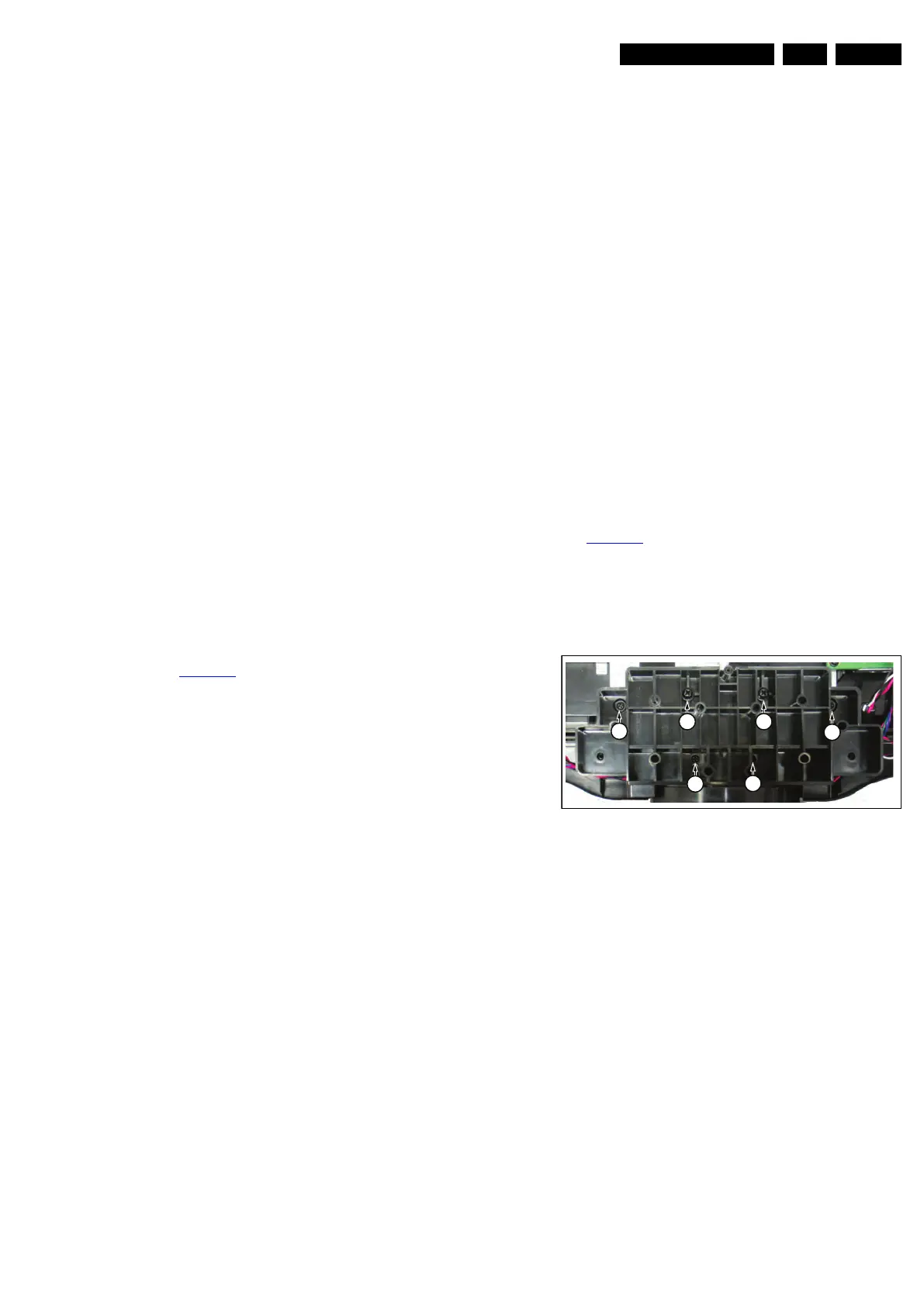
4.5.4 Stand removal
See Figure 4-7
.
Caution: it is mandatory to remount all different screws at their
original position during re-assembly. Be sure to put the set in
the Service Position.
1. Remove the fixation screws [1], (Parker).
2. Remove the fixation screws [2], (M4).
3. Take out the stand.
Figure 4-7 Stand (42")
4.5.5 Speakers
1. Unplug the speaker connector from the SSB.
2. Remove the stand, as described earlier.
3. Take the speakers out together with their casing.
When defective, replace the whole unit.
4.5.6 Stand support plate
1. Remove the stand as described earlier.
2. Remove the SSB as described earlier.
3. Remove the PSU as described earlier.
4. Remove all fixation screws from the stand support plate
and take it out of the set.
18850_105_100203.eps
100203
2 2
1
1
1
1