Mechanical Instructions
EN 14 TPM5.1E LA4.
2011-Sep-02
4.5.7 IR/LED Board
1. Remove the stand as described earlier.
2. Remove the speakers as described earlier.
3. Remove the SSB as described earlier.
4. Remove the clips at the bottom that secure the LCD panel
with the bezel.
5. Remove the fixation screws that secure the LCD panel with
the bezel.
6. Lift the LCD Panel from the bezel.
7. Unplug the connectors from the IR/LED board.
8. Release the clips that hold the board and take it from the
bezel.
When defective, replace the whole unit.
4.5.8 Keyboard Control Panel
See Figure 4-8
.
1. Remove the stand as described earlier.
2. Remove the speakers as described earlier.
3. Remove the SSB as described earlier.
4. Remove the clips that secure the LCD panel with the bezel.
5. Remove the fixation screws that secure the LCD panel with
the bezel.
6. Lift the LCD Panel from the bezel.
7. Unplug the connector [1] from the Keyboard Control Panel.
8. Release the clips that secure the Keyboard Control
Panel [2].
When defective, replace the whole unit.
Figure 4-8 Keyboard Control Panel (42")
4.5.9 LCD Panel
1. Remove the stand as described earlier.
2. Remove the speakers as described earlier.
3. Remove the SSB as described earlier.
4. Remove the PSU as described earlier.
5. Remove the Stand support as described earlier.
6. Remove the clips that secure the LCD panel with the bezel.
7. Remove the fixation screws that secure the LCD panel with
the bezel.
8. Lift the LCD Panel from the bezel.
When defective, replace the whole unit.
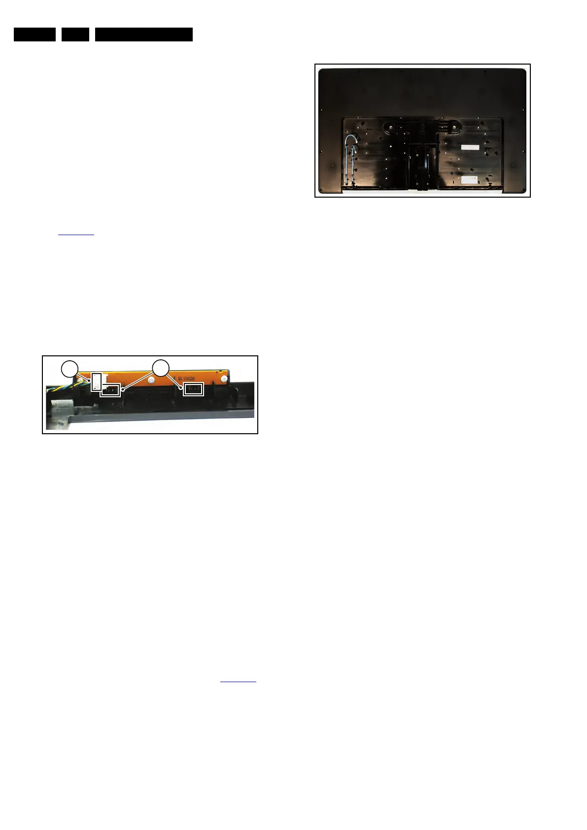
4.6 Returning a defect 32" or 42" Dali styling,
LCD panel
To return a defect LCD panel to the factory, all boards, cabling,
mechanical supports, shieldings, clamps, spacers, the bezel
and tapes have to be removed from the panel, see Figure 4-9
.
Be sure to carefully pack the area’s of the panel that are visible
during normal use.
Figure 4-9 LCD panel
18850_104_100203.eps
100203
2
1
18931_100_100510.eps
100510