Mechanical Instructions
EN 12 VES.2.2E LA4.
2013-Jul-19
back to
div. table
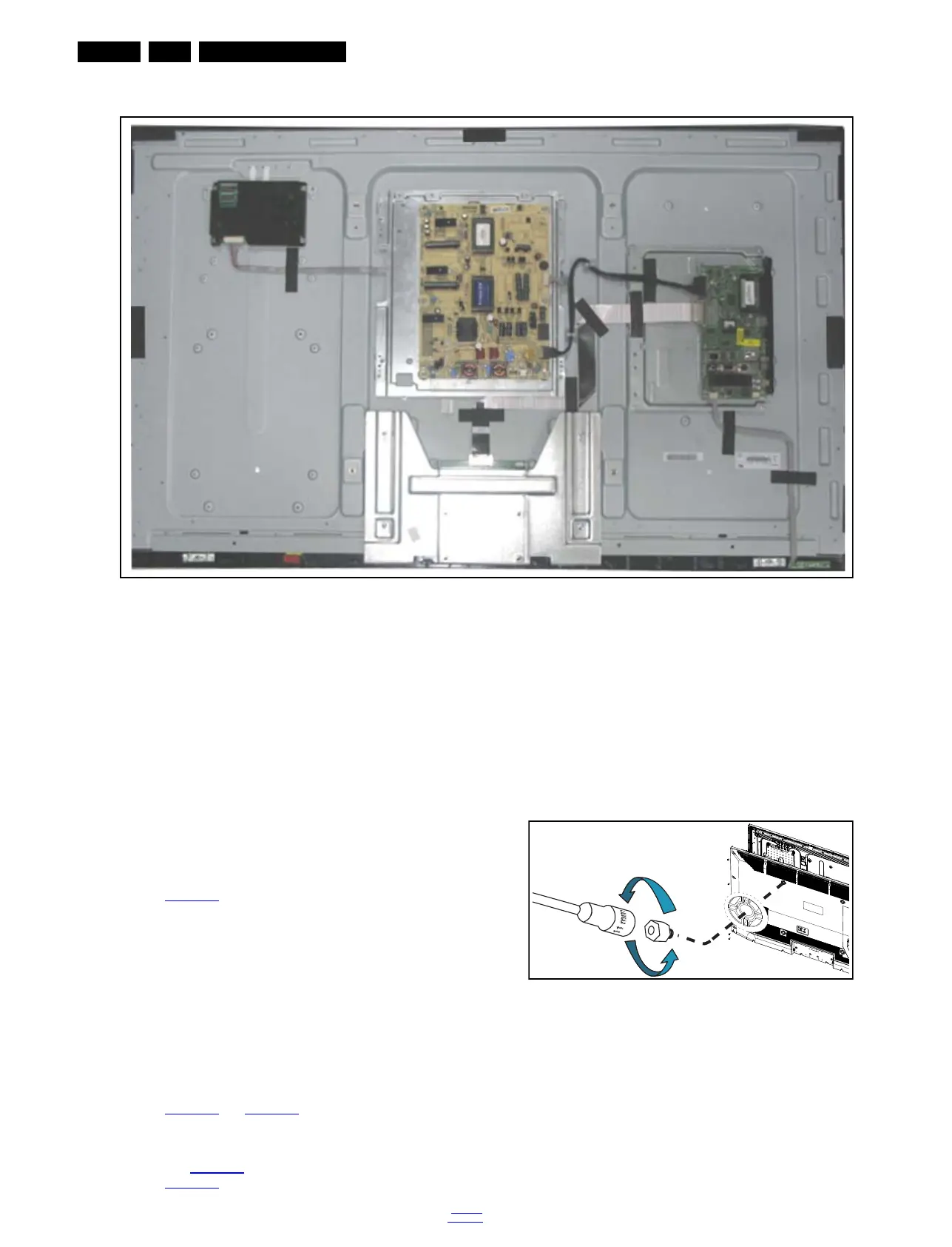
Figure 4-4 Cable dressing (50" 3000 series)
4.2 Service Positions
For easy servicing of a TV set, the set should be put face down
on a soft flat surface, foam buffers or other specific workshop
tools. Ensure that a stable situation is created to perform
measurements and alignments. When using foam bars take
care that these always support the cabinet and never only the
display. Caution: Failure to follow these guidelines can
seriously damage the display!
Ensure that ESD safe measures are taken.
4.3 Assembly/Panel Removal
Instructions below apply to the 32PFL3606H/12, but will be
similar for other models.
4.3.1 Rear Cover (32" to 40")
Refer to Figure 4-6
for details.
Warning: Disconnect the mains power cord before removing
the rear cover.
1. Remove the screw [1] that secures the power cable.
2. Remove the screws [2] that fixate the stand and remove
the stand.
3. Unscrew all the remaining screws [3] and [4].
4. At the indicated areas [5] the cover is secured by clips. Be
careful with releasing those.
5. Lift the rear cover from the TV. Pay attention to the cable
connected to the loudspeakers, it is a very short cable.
4.3.2 Rear Cover (50")
Refer to Figure 4-5
and Figure 4-6 for details.
Warning: Disconnect the mains power cord before removing
the rear cover.
1. Remove the 4 VESA bolts with a 11 mm socket wrench, as
shown in Figure 4-5
.
2. See Figure 4-6
for the next steps.
3. Remove the screw [1] that secures the power cable.
4. Remove the screws [2] that fixate the stand and remove
the stand.
5. Unscrew all the remaining screws [3] and [4].
6. At the indicated areas [5] the cover is secured by clips. Be
careful with releasing those.
7. Lift the rear cover from the TV. Make sure that wires are not
damaged while lifting the rear cover from the set. Be very
careful while lifting the cover as there are cables connected
to the SSB and PSU boards. Those need to be released
before taking the cover off completely.
Figure 4-5 VESA bolts removal
19421_103_130429.eps
130429
19421_100_1
30514.eps
130514
× 4