Circuit Descriptions
EN 22 VES.2.2E LA7.
2013-Jul-19
back to
div. table
7.2 Power Supply
7.2.1 Power Supply Unit
Before checking other parts first check whether fuse on the
PSU is not broken. Always replace a defective fuse with one
with the correct specifications! This part is available in the
regular market.
Consult the Philips Service web portal for the order codes of the
boards.
The output voltages to the chassis are:
• +5V / +3V3 / 12 V- STANDBY
• +5 V / +12V (on-mode)
• +24V for audio circuit, (on-mode)
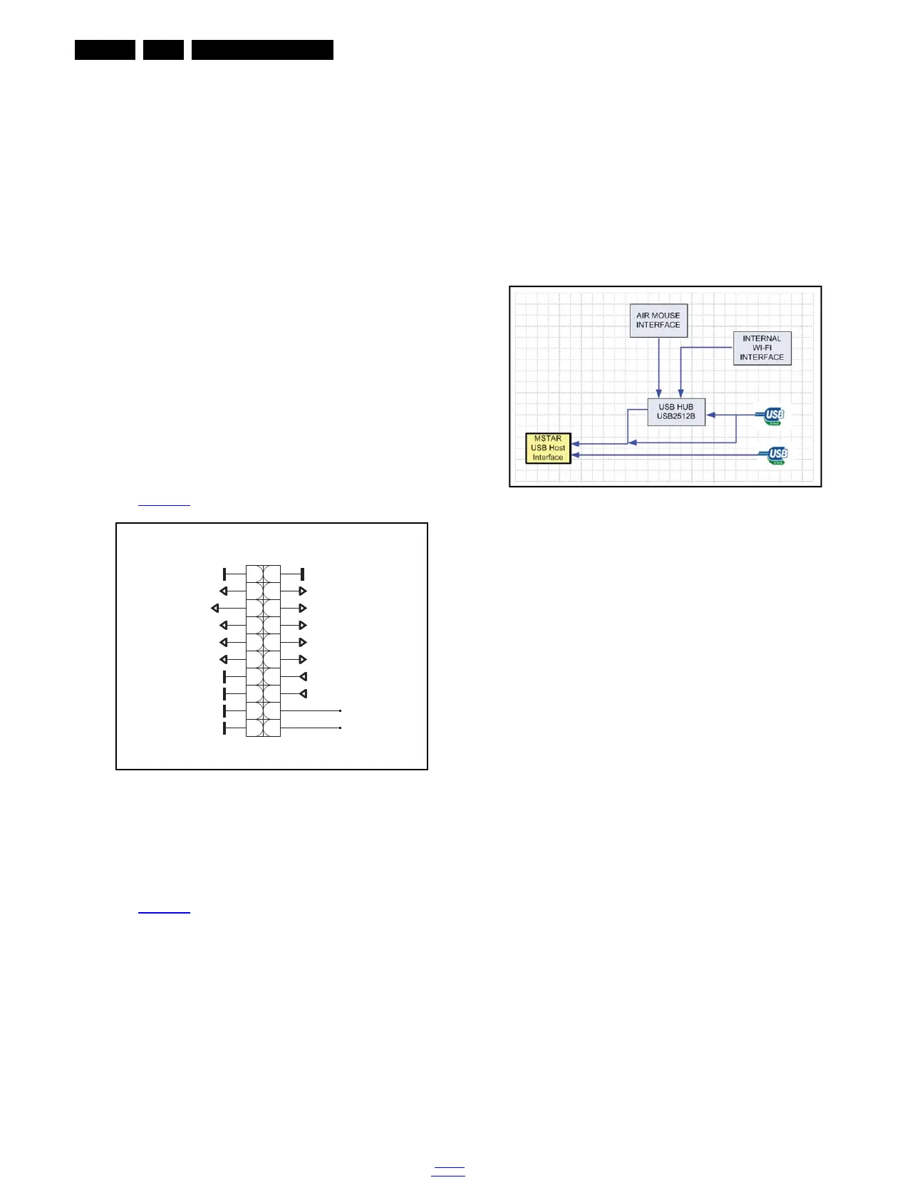
7.2.2 USB Interface
The SOC has two input port for USB, therefore air mouse,
internal wi-fi interface and USB2 are combined with HUB. This
property is optional. If air mouse and wi-fi interfaces are not
aligned, two USB are connected directly to main IC.
7.3 Power Management
The on-board DC/DC converters receive the following voltages
from the PSU (depending on set execution):
• +3.3 VSB, for standby mode.
• +5 VSB, for standby mode.
• +12 VSB, for standby mode.
• +3.3 V, for on mode.
• +5 V, for on mode.
• +24 V, for on mode, audio power.
7.4 Circuit Description
7.4.1 System power
The main board power is received at connector CN2 from
power board, to receive the power and signals from the PSU.
See Figure 7-3
for the correct pining.
Figure 7-3 Connector CN2 overview
7.4.2 System power
The main board power is received at connector CN2 from
power board, to receive the power and signals from the PSU.
See Figure 7-3
for the correct pining.
Figure 7-4 USB Interface
19420_205_130315.eps
130315
CN2
12
34
56
78
910
1112
1314
1516
1718
1920
24V_VCC_AU
DIMMING
BACKLIGHT_ON/OFF
5V_STBY
3V3_STBY
5V_VCC
5V_VCC
12V_STBY
12V_STBY12V_STBY
3V3_VCC
3V3_VCC
power_pin3
power_pin1
power cable
19420_206_130315.eps
130315