BL2 ...1000/2000/7000
12/36
PHOENIX CONTACT 3799_en_D
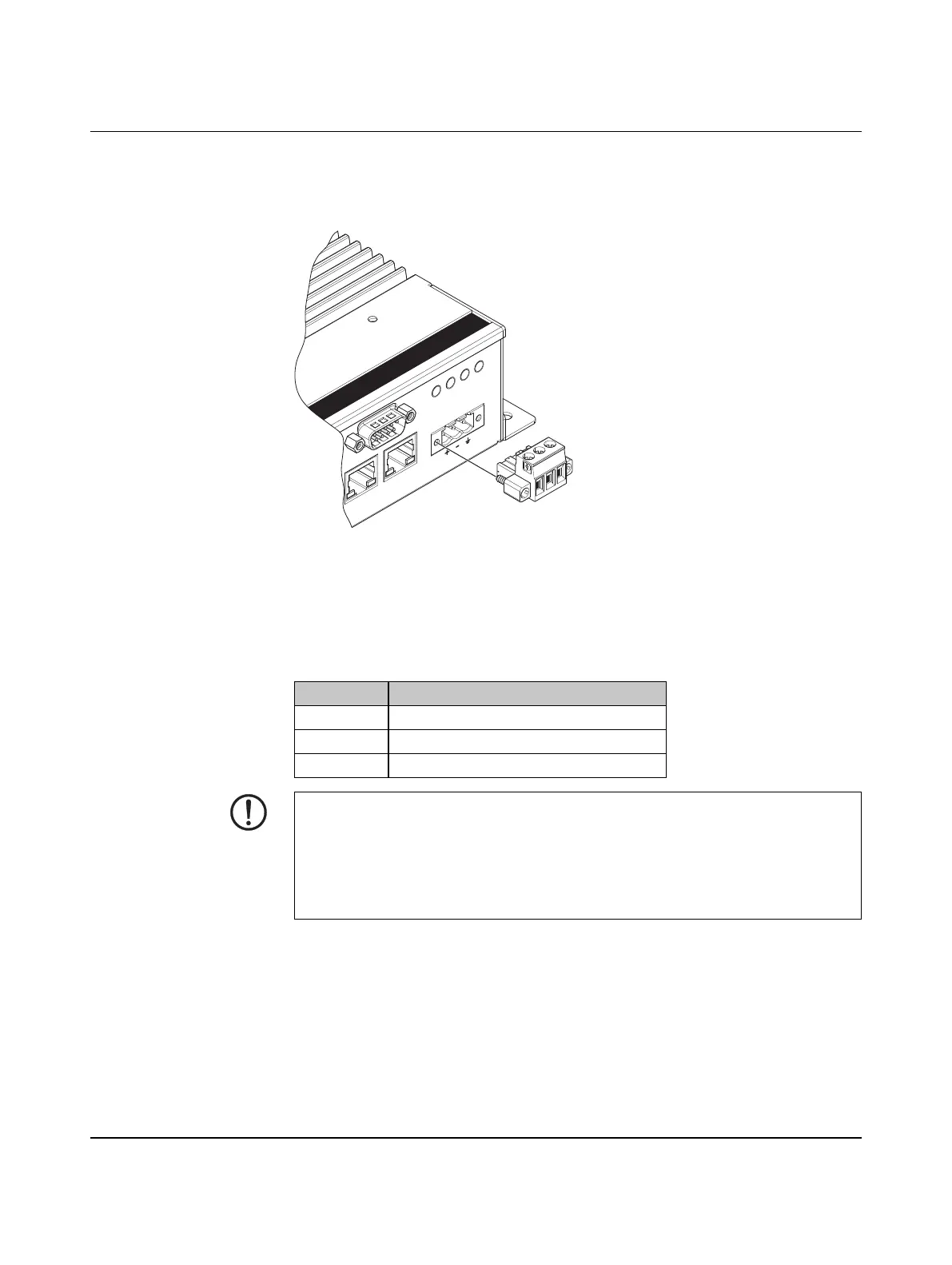
3.2.1 Power connection
A three-position, screw-type COMBICON connector (MSTB 2,5/ 3-STF-5,08) is provided
for connecting power to the BL2 ...1000/2000/7000.
Figure 3-7 Power connector
Connect a power source to the included power connector. This connector supports wire
sizes from 0.2 to 2.5 mm² (24 to 12 AWG). Torque the wire-retaining screws in the
connector to 0.5 Nm (4.4 lb
f
-in.). Secure the connector to the BL2 ...1000/2000/7000
chassis.
Table 3-2 Power connector
Pin No. Description
6 Ground
– 0 V DC
+ 24 V DC ±20%
X11: CO
M
X12: COM
X4: USB
X5: USB
X2: ETH
ERROR R
UN SATAPWR
X1: PWR
24VDC
X3: ETH
NOTE:
To ensure safe operation, use safety extra-low voltage (SELV) according to DIN EN 61131
as supply voltage.
This device is protection class I item of equipment.
UEFI is set to boot on power, allowing the system to boot as soon as the power plug is
installed. This can be changed in the UEFI.