Maintenance
3799_en_D PHOENIX CONTACT 21/36
6. Reconnect the power connector and apply power. During the boot process, a message
will appear notifying the user that the CMOS and UEFI settings have been reset to the
factory defaults.
7. During the boot process, press the <F2> key to access the UEFI settings (see “UEFI”
on page 22).
8. Update the UEFI configuration with any appropriate user-defined requirements.
5.4 Mass storage
The mass storage device is a solid-state drive (SSD) with an M.2 interface.
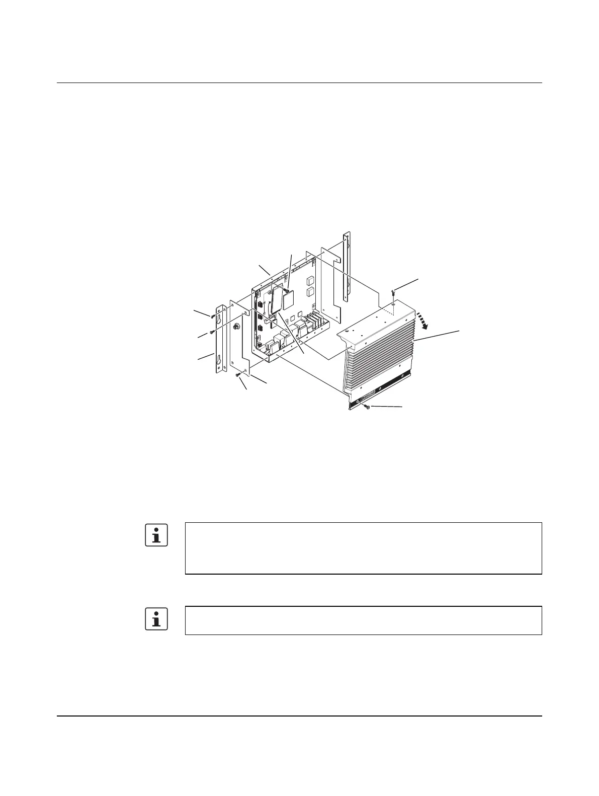
Figure 5-5 Drive replacement
To replace a drive:
1. Turn off the IPC and disconnect power.
2. Remove the two screws (1) securing the mounting bracket (2). Repeat for the other
side.
3. Remove the two screws (3) holding the side panels (4) to the chassis (5). Repeat for the
other side.
4. Remove the three screws (6) across the label on the top of the heat sink (7).
5. Remove the two screws (8) across the top of the heat sink and remove the heat sink.
6. Locate the M.2 SSD (9) on the board. Remove the screw (10) that secures the drive in
the socket.
6
2
3
4
7
1
3
5
8
9
10
The heat sink may be able to be removed if one side panel is removed and the other is
loosened.
If equipped with a wireless miniPCI card, the internal cable does not need to be
disconnected if care is taken when handling the side panel.
Thermal pads between the board and heat sink may cause resistance when removing the
service panel.