Installation
3799_en_D PHOENIX CONTACT 13/36
3.2.2 Serial communication
One D-SUB 9 connector (see Figure 3-6) can be configured to communicate on the
RS-232, RS-422, or RS-485 physical layer. The physical layer is set using the UEFI (see
“UEFI” on page 22). The remaining connectors are limited to RS-232 only.
The BL2 ...1000/2000/7000 is capable of the following communication parameters:
The function of the pins in the D-SUB 9 connector varies with the different configuration
settings.
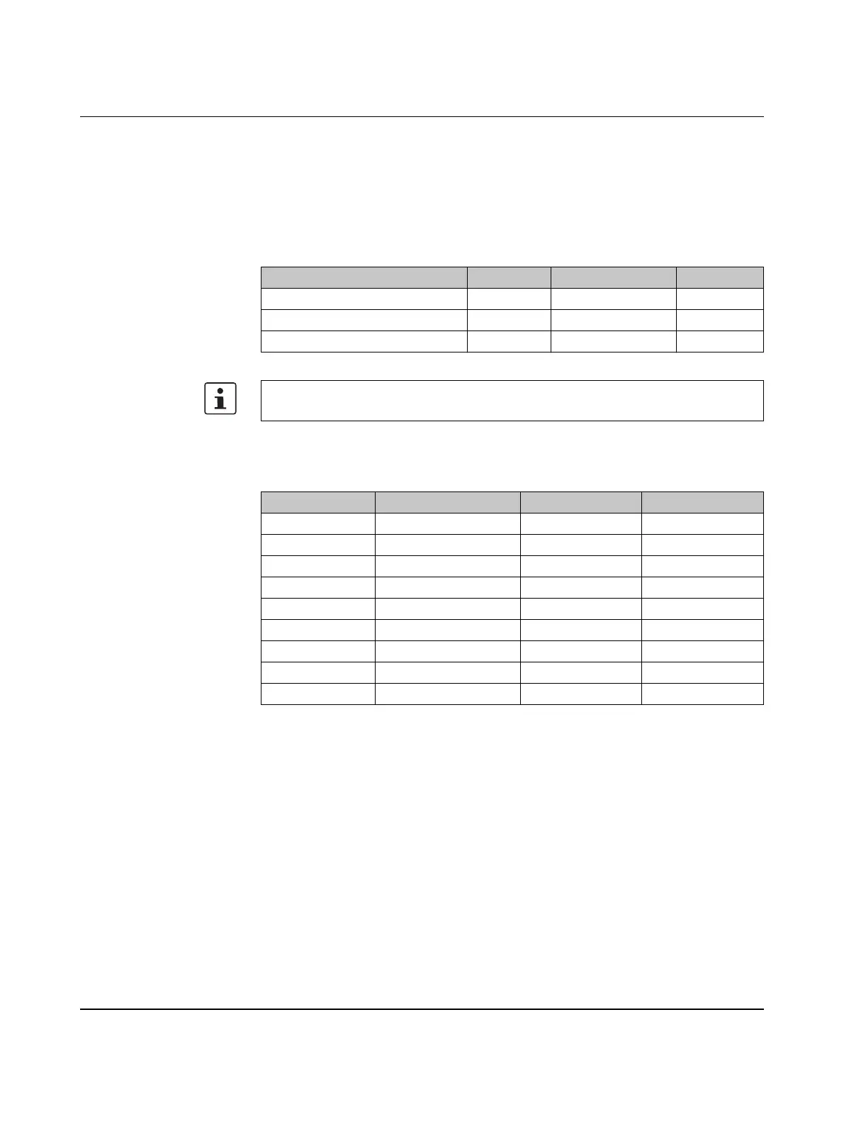
Table 3-3 RS-232/422/485 communication settings
Data bits Parity Stop bits
RS-232 7/8 None/Even/Odd 1/2
RS-422/485 Autotoggle RTS 8 None/Even/Odd 1/2
RS-422/485 Manual RTS 7/8 None/Even/Odd 1/2
The table shows the capabilities of the IPC. Configuration of parameters to communicate
with a specific device is typically part of the software tool performing the communication.
Table 3-4 D-SUB 9 pinout
D-SUB 9 pin RS-232 RS-422 RS-485
1 DCD TXD- TXD-/RXD-
2 RXD TXD+ TXD+/RXD+
3 TXD RXD+ –
4 DTR RXD- –
5 GND GND GND
6 DSR – –
7 RTS – –
8 CTS – –
9 Ring indicator – –