Do you have a question about the Phoenix Contact CBMC E4 24DC/1-10A IOL and is the answer not in the manual?
Explains symbols and signal words for hazards and property damage.
Specifies the required qualifications for users of the product.
Outlines the purpose of the user manual and the products it covers.
Lists the necessary hardware components for operating the device.
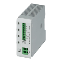
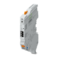
Provides an overview of the multi-channel circuit breaker's function and features.
Describes the multi-functional channel LED button and its operation modes.
Details how to operate the device without an IO-Link connection.
Explains the requirements and operation procedures for IO-Link connectivity.
Covers mounting location, DIN rail mounting, removal, and mounting position for optimal cooling.
Explains how channels are controlled and nominal currents are changed via cyclic process output data.
Presents detailed technical specifications including dimensions, ambient conditions, and general properties.
Provides a list of all figures included in the document with their respective page numbers.
| Rated Voltage | 24 V DC |
|---|---|
| Rated Current | 1-10 A |
| Mounting Type | DIN Rail |
| Output Current | 1-10 A |
| Connection Method | Push-in connection |
| Number of Channels | 4 |
| Interface | IO-Link |
| Number of Poles | 1 |
| Trip Characteristic | Electronic |
| Connection Type | Push-in connection |
| Housing Material | Plastic |
| Protection Class | IP20 |
| Input Voltage Range | 18 V DC to 30 V DC |
| Operating Temperature | -25°C to 70°C |
| Type | Electronic circuit breaker |