ESPAÑOL
16 17
3.2. Conexión RS-232
Efectuar un cableado de 1 a 1 entre el
módulo PSM y el aparato periférico según
fig. 8. El cable puede ser un cable están-
dar RS-232 usual.
Nota: Para la configuración mínima
se necesita una conexión de
TxD, RxD y GND
(software handshake)!
3.3. Sostén CTS/RTS
Según sea necesario, también pueden
transmitirse las líneas de mando CTS/RTS
junto a las líneas de datos TxD y RxD (fun-
ción de 4 canales; ver esquema funcional
fig. 9).
• Las líneas de mando DSR/DTR están
puenteadas internamente en fijo.
Condición: dichas líneas están cablea-
das en el cable RS-232 (fig. 8).
3.4. Indicador de datos (fig. 10)
Dos LEDs de diagnóstico señalizan los
tipos de servicio del interface RS-232
• amarillo: emitir datos, dinámicamente
• verde: recibir datos, dinámicamente
4. Adaptación del interface RS-232
Abrir: con un destornillador, encajar en el
punto marcado en rojo de la tapa y desen-
cajarla hacia arriba.
El interruptor S1 se halla debajo de la tapa
de la caja, en el punto marcado (fig. 11).
• Conmutación DTE/DCE (figs. 12/13)
Por medio del interruptor S1 se pueden
cruzar las conexiones TxD y RxD y las co-
nexiones RTS y CTS internamente, de
manera que la adaptación se puede efec-
tuar confortablemente.
Más respecto a la adaptación del interface en la
pág. 19
FRANÇAISENGLISH
3.2. RS-232 Connection
For a one-to-one wiring of the PSM mod-
ule and the peripheral device, assemble
the connection cable as shown in Fig. 8.
This can be a commercially available
standard RS-232 cable.
Note:For a minimum configuration, you
need to connect TxD, RxD and GND
(software handshake)!
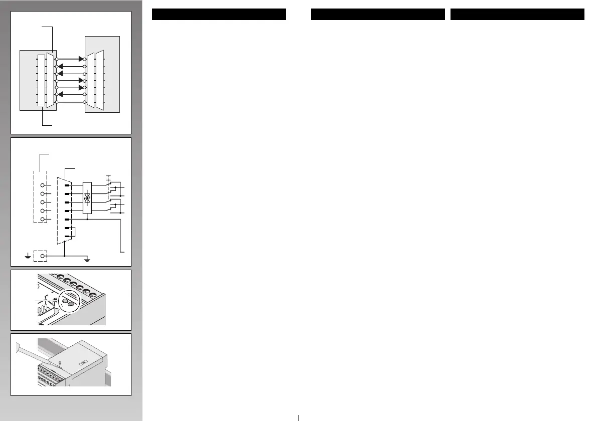
3.3. CTS/RTS Support
If necessary, you can transmit the control
lines CTS/RTS along with the data lines
TxD and RxD (4-channel function; see
functional circuit diagram detail, Fig. 9).
• The control lines DSR/DTR are perma-
nently bridged internally!
Prerequisite: In the RS-232 cable, these
lines must be wired as well (Fig. 8)!
3.4. Data Indicator (Fig. 10)
Two diagnostic LEDs indicate the RS-232
interface modes
• Yellow: Transmit data, dynamic
• Green: Receive data, dynamic
4. RS-232 Interface Adaptation
Opening: Open the cover with a screw-
driver inserted at the marked point and
raise the cover.
The switch S1 is located at the marked
point under the housing cover (Fig.11).
• DTE/DCE Switchover (Fig. 12/13)
Switch S1 is used to cross the TxD and
RxD connection and the RTS and CTS
connection internally, allowing the adapta-
tion to be carried out conveniently.
Further details for the interface adaptation,
see page 18!
3.2. Connexion de l'interface RS 232
Réaliser un câblage point à point entre le
module PSM et l'appareil de la périphérie
selon la fig. 8. On peut utiliser pour cela
un câble RS 232 standard du commerce.
Remarque: pour une configuration mini-
male,vous aurez besoin des
lignes TxD, RxD et GND
(Software handshake)!
3.3. Support CTS/RTS
Le cas échéant, les lignes de commande
CTS/RTS peuvent transmettre à côté des
lignes de donnéesTxD et RxD (fonction 4
canaux; voir schéma fonctionnel, fig.9).
• Les lignes de commande DSR/DTR
font l'objet d'un pontage interne fixe !
Pour cela, ces lignes doivent être
câblées dans le câble RS-232 (Fig.8)!
3.4. Indicateur de données (Fig. 10)
Deux LED de diagnostic indiquent le mode
de fonctionnement de l'interface RS-232
• jaune: émission de données, active
• vert: réception de données, active
4. Adaptation de l'interface RS-232
Ouverture: Insérez un tournevis dans
l'encoche du capot et dégagez ce dernier
en le soulevant vers le haut.
Le commutateur S1 est situé au endroit in-
diqué sous le capot du boîtier (Fig.11).
• Commutation DTE/DCE (Fig. 12/13)
Le commutateur S1 permet de croiser les
lignes TxD et RxD et les lignes RTS et
CTS à l'intérieur, ce qui rend la procédure
de commutation particulièrement aisée.
Autres renseign. sur adaptation de l'interface,
v. p. 19!
RS232
RS232
4
5
7
8
9
V
N
C
T
x
D
R
x
D
C
T
S
R
T
S
G
N
D
R
S
2
3
2
Art.-Nr. 27 61 26 6
Fig.10
LEDs
4
TxD
8
5
RxD
3
8
7
2
7
6
DTE
DCE
4
6
5
RTS
CTS
GND
DSR
DTR
Fig.9
PSM-EG-RS-232
SUB-D 15
COMBICON /
MINICONNEC
S1
Fig.11
N
C
T
S
2
D
T
E
S
1
D
C
E
TxD
RxD
CTS
RTS
DTR
DSR
GND
3
2
8
7
4
6
5
4
5
6
7
–
–
8
SUB D
9
2
3
5
4
20
6
7
3
2
8
7
4
6
5
TxD
RxD
CTS
RTS
DTR
DSR
GND
25
Max.
15 m
Peripherals Side
Côté périphérie
Lado perifería
PSM-EG-RS232…
Fig.8
COMBICON /
MINICONNEC
SUB-D9
(Female)
(femelle)
(hembra)

 Loading...